
Voltage to Frequency Converter Using UJT
The voltage to frequency converter circuit operates by converting an input voltage into an output frequency. In this design, a UJT oscillator is employed, which is known for its simplicity and effectiveness in generating oscillations. The UJT is characterized by its three terminals: the emitter (E), and two base terminals (B1 and B2).
The timing capacitor, C2, plays a crucial role in determining the frequency of oscillation. As the input voltage varies, it influences the charge and discharge cycles of C2. The UJT oscillator operates by charging C2 through a resistor until the voltage across C2 reaches a certain threshold, at which point the UJT turns on, discharging C2 rapidly and generating a pulse. This cycle repeats, producing a continuous output frequency that corresponds to the input voltage level.
The frequency output can be adjusted by varying the resistance in the charging path or by changing the capacitance value of C2. This flexibility allows for a wide range of frequency outputs based on the input voltage, making the V/FC circuit suitable for various applications, including signal processing and frequency modulation.
Overall, the UJT oscillator configuration in the voltage to frequency converter circuit provides a straightforward and efficient method for frequency generation based on varying input voltage levels.The following voltage to frequency converter (V/FC - VCO) circuit consist of a UJT (uni-junction transistor) oscillator in which the timing charge capacitor C2.. 🔗 External reference
Related Circuits
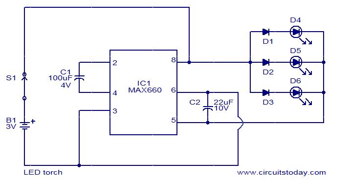
This is a simple LED torch circuit based on the MAX660 integrated circuit from MAXIM semiconductors. The MAX660 is a CMOS monolithic voltage converter IC capable of driving three bright white LEDs connected in parallel to output pin 8....
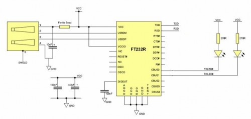
Some still remember the serial RS232 port, also referred to as a COM PORT, as its functionality has largely been replaced by USB ports. However, for electronics engineering students and technicians learning about computer interfaces, the RS232 port remains...
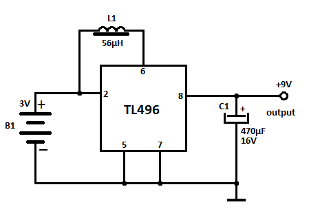
This document presents several DC converter circuits that convert input voltages from 3V to 9V. These converters can be particularly useful in scenarios where a 9V battery is not available or deemed too costly. The first circuit is straightforward,...
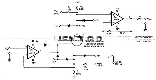
This amplifier can transfer DC to 5 MHz signals across a potential difference of 25,000 V. It can be utilized in CRT displays and high-voltage applications. It is important to note that the tube must be shielded due to...
This decibel meter circuit responds to sound pressure levels ranging from approximately 60 to 70 dB (decibels). The sound is captured by an 8-ohm speaker and amplified using a transistor stage along with an LM324 operational amplifier section. A...
This document outlines a basic circuit designed to power high impedance, high voltage, low current devices such as electroluminescent (EL) backlights and fluorescent tubes. The project originated from the need for a simple yet flexible inverter circuit for an...
Warning: include(partials/cookie-banner.php): Failed to open stream: Permission denied in /var/www/html/nextgr/view-circuit.php on line 713
Warning: include(): Failed opening 'partials/cookie-banner.php' for inclusion (include_path='.:/usr/share/php') in /var/www/html/nextgr/view-circuit.php on line 713