
Low-power inverter using LM555 Timer IC
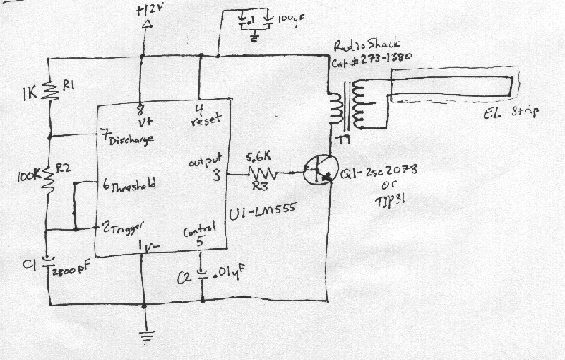
The circuit is centered around the 555 timer, configured in astable mode to generate a square wave signal. This signal drives a medium-power transistor, such as the 2SC2078 or TIP31, which acts as a switch to control the flow of current through the transformer. The transformer serves to step up the voltage from the 12-volt supply to the required high voltage for the EL backlight or fluorescent tube. The use of a capacitor (47µF) in conjunction with the transformer smooths the output waveform, ensuring that the voltage remains stable and reduces the risk of damaging the connected devices.
To achieve optimal performance, careful consideration is given to the transistor biasing resistors, particularly R3, which may need adjustment based on the specific transistor used and the desired brightness of the output. The circuit design allows for flexibility, enabling modifications to accommodate different types of EL strips or fluorescent tubes by simply adjusting component values.
The final assembly of the circuit on perfboard ensures a compact and durable design, suitable for integration into various applications, including media PCs. The choice of power supply is also crucial; utilizing a standard ATX power supply with Molex connectors simplifies the connection process and enhances compatibility with existing systems. The use of 18-gauge zip cord for power distribution allows for convenient placement of the EL backlight without concern for the display's location.
Overall, this inverter circuit is a practical solution for powering high voltage, low current devices, offering reliability, ease of assembly, and cost-effectiveness.This document describes a basic circuit that can be used to power high impedance, high voltage, low current devices such as EL backlights and fluorescent tubes. This project got its genesis when I needed a simple, yet flexible inverter circuit for an EL backlight, using a 12 volt input.
My specific need was to power the backlight for the wildly po pular LCD-107 ( specs ) from All Electronics Corporation. However, this circuit is versatile enough that it should be able to power any EL strip or small (up to a few watts) fluorescent tube. Why build instead of buy an inverter Well, I actually bought one from one of the several surplus resale houses out there.
It was apparently very poorly designed. I connected it to the backlight contacts, then to the +5V recommended, only to get a brief buzzing noise and some smoke for my trouble. I decided I could build a much more reliable, versatile inverter for just a few dollars (total cost is only about $6 for the semiconductors and transformer at your local Radio Shack), and set out to do it.
It occurred to me that a simple 555 timer with a small step-up transformer should work well. The 555 timer is now ubiquitous, available on nearly any street corner via Radio Shack. For the transformer, many circuits use a filament transformer or other step-down transformer generally designed for use in a utility power supply. This wouldn`t do - it would be too large and cumbersome for my needs, and besides, I didn`t have a need for Big Power.
I`d had good luck in the past using 8 ohm to 1k ohm audio output transformers in "tickle stick" inverter-type applications, so I thought this might work if driven with a good oscillator. I initially setup the circuit for 400Hz operation, with the timer driving the transformer directly through a 47uF capacitor.
This worked, although the display was fairly dim. After experimenting with various frequencies, I decided to add a medium-power transistor driver stage. This worked wonders! The base current and drive frequency were then tweaked to make the transistor run nice and cool, while maintaining optimum brightness on the backlight.
The final circuit parameters generate about 127 AC volts RMS, at about 2. 5kHz. With these specifications, the transistor barely warms at all, and current consumption is about 110 mA at 12 volts input. The EL backlight is VERY bright! Notice in the image to the left, the soft green-blue glow of the display. There are three LEDs (two Reds and a Green) attached to the power supply input to give an idea of relevant brightness.
The 2sc2078 did not even require a heat sink with this design. The TIP31 is a slightly more rugged design, and might have slightly different electrical characteristics - notably, you might need to experiment a little with R3 by increasing value by a few K if the transistor gets too warm, or decrease the value by a few K if the transistor is cool but the display`s too dim. See the circuit notes for more info. For the final version, I wanted to go from breadboard to perfboard, and make a few other changes. Because this was destined for a Media PC, I wanted to be able to power it from a standard ATX power supply.
The power cord from a failed 80mm fan solved that problem; it has the requisite "in-line" Molex-style power connectors, with a tap from the 12 volt line. I also wanted to make sure the power supply for the EL backlight could be placed with little consideration for the display location itself.
A length of 18 gauge zip cord solved that. The completed version is comparable in size, and quite superior in performance to the original el-cheapo. Best of all, this design is easy and fun to build, using readily available components. And look ma, no smoke! 🔗 External reference
Related Circuits
If you have ever used a 12V flasher relay system, typically a mechanical type, for general automotive applications, today we will attempt to build a 12V flasher relay circuit. The 12V flasher relay circuit is a crucial component in automotive...
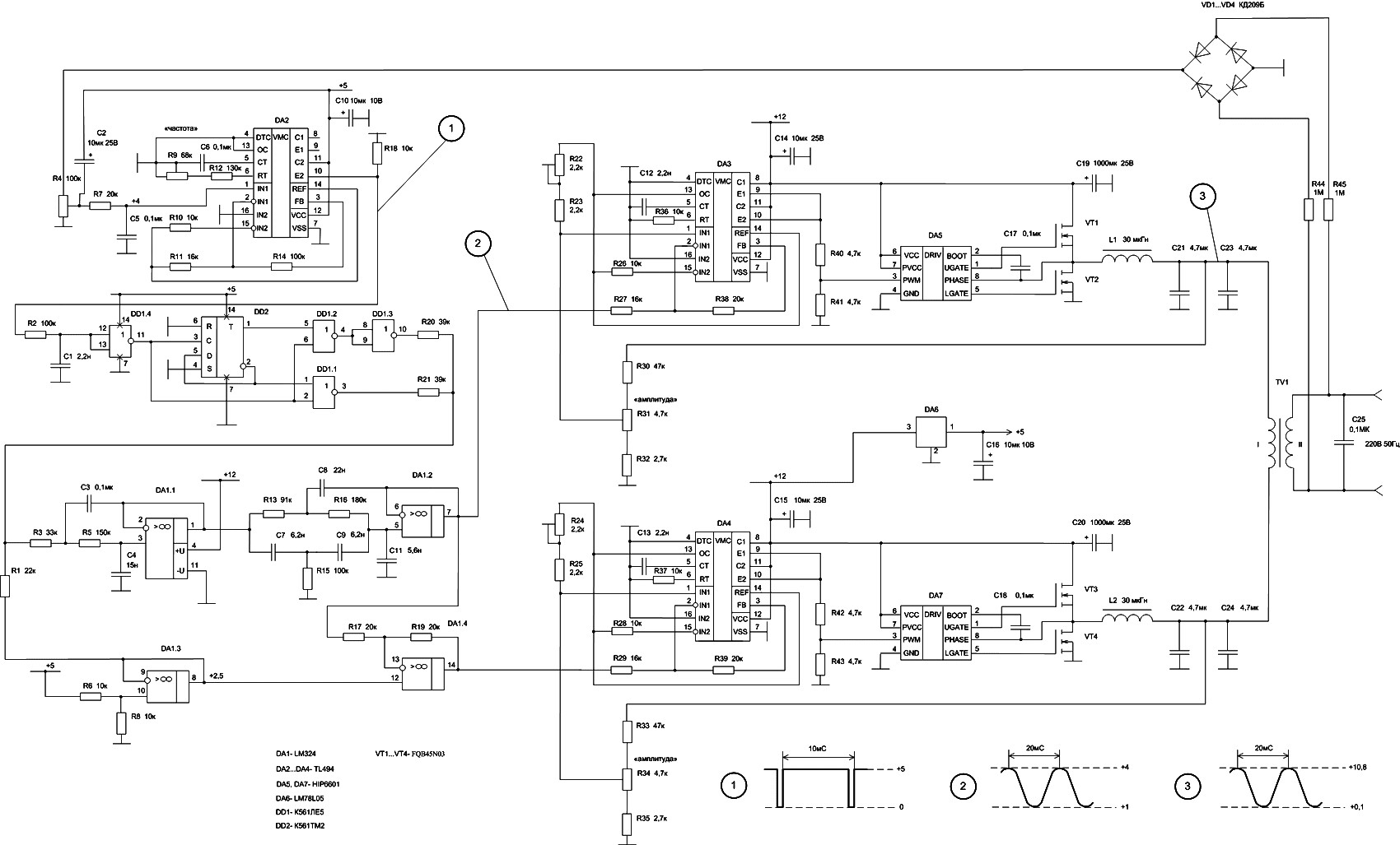
In DA3, DA5, VT1, and VT2, the first channel of the VLF Class D amplifier is assembled. The second channel is constructed using DA4, DA7, VT3, and VT4. Antiphase sine waves in the VLF range are formed at the...
How can a circuit be built for digital readout of three-phase power consumption in a home using a chip like ADE7762? There is an interest in polyphase energy metering. To construct a circuit for digital readout of three-phase power consumption...
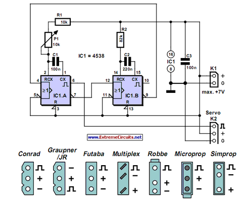
Individuals who frequently work with servos are likely familiar with situations where a servo tester is beneficial. The primary function of a servo tester is to produce a pulsing signal with a variable positive pulse width ranging from 1...
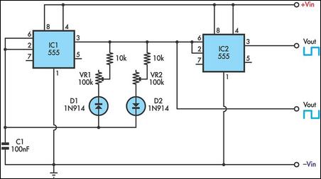
This timer utilizes two 555 integrated circuits (ICs) to adjust the desired output. The variable resistors VR1 and VR2 serve as potentiometers to modify the cycle speed. The circuit can be powered with a 9 to 12-volt power supply,...
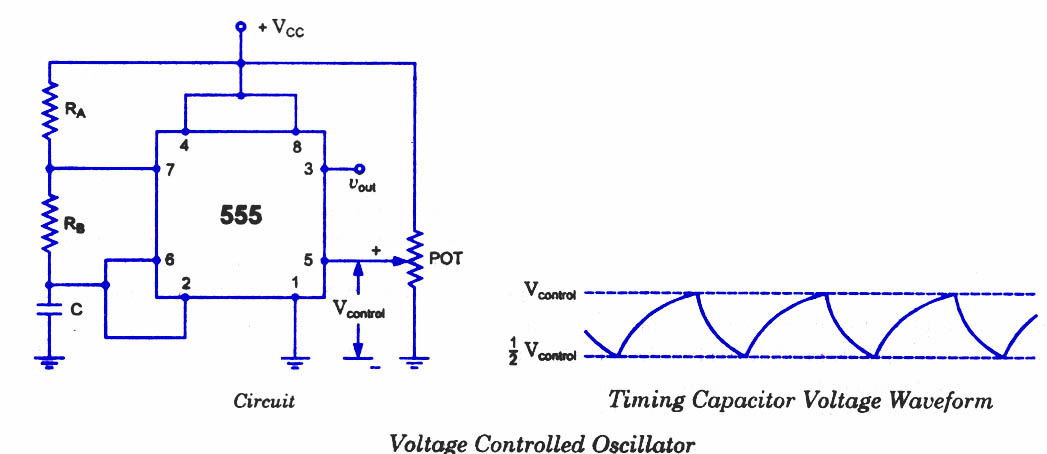
As discussed in previous blog posts, the pin 5 terminal serves as a voltage control terminal, allowing for the adjustment of threshold and trigger levels. Typically, the control voltage is set at +2/3VCC due to the internal voltage divider....
Warning: include(partials/cookie-banner.php): Failed to open stream: Permission denied in /var/www/html/nextgr/view-circuit.php on line 713
Warning: include(): Failed opening 'partials/cookie-banner.php' for inclusion (include_path='.:/usr/share/php') in /var/www/html/nextgr/view-circuit.php on line 713