
Voltage-Tuned Vhf Oscillator
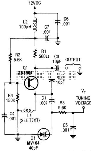
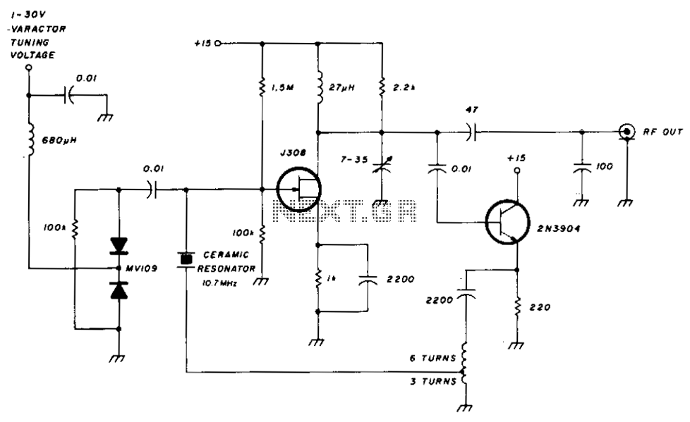
This VHF Voltage-Controlled Oscillator (VCO) circuit is designed to generate frequencies in the Very High Frequency (VHF) range, specifically from 30 MHz to 200 MHz. The core component, Q1, is a transistor that can be replaced with a 2N3563 for applications requiring operation above 100 MHz. This substitution allows for enhanced performance at higher frequencies, ensuring the circuit maintains stability and efficiency.
The inductor, L1, is a critical element in the circuit, as it is tuned to resonate with the varactor diode's capacitance. In this design, a varactor with a capacitance of 40 pF is employed, which allows for fine-tuning of the output frequency. The choice of the varactor is essential, as it directly influences the frequency modulation capabilities of the VCO. For applications demanding higher linearity in frequency response, the circuit can accommodate alternative varactor models or utilize two varactors arranged in a back-to-back configuration. This arrangement can significantly enhance the linearity of the tuning curve, making the VCO more suitable for precision applications.
To implement this VCO effectively, careful consideration must be given to the selection of passive components, including the inductor and the varactor, to ensure optimal performance across the desired frequency range. Additionally, layout considerations such as minimizing parasitic capacitance and inductance are vital for maintaining signal integrity and reducing unwanted oscillations. Overall, this VHF VCO circuit presents a versatile solution for various RF applications, including communication systems, signal generation, and frequency synthesis. This VHF VCO circuit is suitable for 30 to 200 MHz. Q1 can be replaced by a 2N3563 for operation above 100 MHz . LI is chosen to resonate to the desired frequency with the varactor capacitance of 40 pF. Other varactors can be substituted or two back-to-back varactors can be used for better linearity, depending on the application. 🔗 External reference
Related Circuits
A 50 kHz circuit is feasible due to its nearly ideal characteristics. The 50 kHz circuit is designed to operate effectively within that frequency range, leveraging components that exhibit minimal parasitic effects and optimal linearity. The circuit may include...
This CMOS square-wave oscillator utilizes the 4047 multivibrator circuit, suitable for both monostable (one-shot) and astable applications. In the provided configuration, the 4047 operates as an astable multivibrator. The circuit features three outputs from the 4047, with the first...
The world is full of xtal oscillators twiddled by digital designers lacking in the analog design knowledge necessary. Just look at all the PC real time clocks that lags or leads by several minutes per day. And they eat...
The FET input amplifier utilizes fixed bias with source feedback, resulting in a very high input impedance and low capacitance. An emitter follower is driven by the FET amplifier, which, despite its low output impedance, feeds a transformer with...
This Hartley oscillator was constructed using a single 45 tube and is based on a design published in a 1932 QST article by George Grammer. The initial circuit experienced performance issues due to weak 45 tubes, necessitating a very...
This circuit is a conventional Pierce type oscillator that utilizes a JFET. It operates with fundamental mode crystals and exhibits good performance and reliability when a low noise JFET is employed. The feedback is regulated by the capacitance of...