
Single 10 Shunt Fed Hartley Oscillator for 80 meter CW
This Hartley oscillator circuit is a classic example of early radio technology, showcasing the use of vacuum tubes for signal generation. The design emphasizes simplicity and functionality, making it an ideal project for amateur radio enthusiasts interested in vintage equipment. The choice of components, such as the 10 triode, reflects the preferences of the era, where specific tubes were favored for their performance characteristics in radio transmission.
The tank coil, constructed from copper tubing, not only serves its electrical function but also contributes to the aesthetic appeal of the device, aligning with the vintage theme. The use of porcelain insulators and Pfanestock clips further enhances the historical authenticity of the build. The integration of a variable capacitor for antenna coupling allows for fine-tuning of the output signal, which is critical for achieving optimal performance in amateur radio applications.
Moreover, the circuit's adaptability to different filament voltages indicates versatility, allowing for broader use in various setups. The careful consideration given to the coupling mechanism and the need for stability during operation highlights the engineering principles that underpin effective radio transmission. Overall, this Hartley oscillator serves as a functional piece of equipment while also embodying the craftsmanship and design ethos of early 20th-century radio technology.This Hartley oscillator was built on the remains of a single tube Hartley using a single 45. The original circuit I constructed was one that was published in a 1932 QST article by George Grammer. As it turned out, both of the 45s I had were weak, so the oscillator only would run when it was loaded very, very lightly.
I did, however, have a good 10 triode, so I decided to change the value of the grid leak and the element voltages accordingly, and stick a 10 in the circuit. The 10 was a very popular tube in the late 20`s and early 30s for use in simple amateur radio transmitters.
Sterlings "Radio Manual", second edition, 1929, has a section devoted to a shunt-fed hartley oscillator using a 10 triode. This same book, incidentally, has a section devoted to a simple three tube regenerative receiver, using tube base coils.
You can build a complete 1929 station with the info in this book! Anyway, this tube oscillated easily and I was able to get 5 watts, output, when loaded, using 300 VDC on the plate. But, on key-up, the tube drew a slight amount of current, which turned out to be a parasitic oscillation.
I was, however, quite happy with the output power and efficiency of the 10 in this circuit. My success with the shunt-fed design using 27s, shown elsewhere on this site, convinced me to re-build the Grammer Hartley using a 10 in the shunt-fed configuration. I wanted to change my original wire tank coil with more period-looking copper tubing anyway. So, here is the schematic of the single 10 Hartley oscillator: I built the circuit breadboard style on a piece of poplar.
The front panel is a kind of acrylic product that I bought at the local electronics surplus store. It sort of looks like bakelite, which was the appearance I was after. The vintage National Dial I picked up in a box of junk at a hamfest. I used porcelain beehive insulators to support the tank coil. They look great! I used Pfanestock clips for all the external connections, ie, to the HV, key, filament, ground, an antenna. Here are some of the electrical details: tank coil, 12 turns 1/4" copper tubing, 2. 5" diameter. Tank capacitance: 400 pf fixed mica tub + 140 pf air variable ( used for coarse frequency set ) + 25 pf main tuning capacitor.
Grid Leak = 10K. The antenna coupling is built right onto the board, and uses a 250 pf air variable in series with a antenna coupling coil ( it is the coil wound on the black PVC pipe in the photograph of the top of the transmitter, far left ). This coil can rotate to vary the coupling of the antenna to the tank coil. It will tune a 1/4 wave end fed antenna cut for 80 meters. With the tap on the tank coil at 5 turns, the 10 draws about 54 ma at 304 VDC, or 16. 4 watts input. Coupling to the antenna is varied to get 5 watts output to the load. Care must be taken not to overcouple the antenna to the tank, or frequency stability and note will suffer.
Also, the 10 will run just fine on 6. 3 VAC for the filament supply, which is what I use. 7. 5 VAC is nominal for this tube. This Hartley works great. With a 300 VDC plate supply, I can easily get 5 watts of output with little or negligible chirp. It is easy to use and load up into an antenna. When used with the triple 30 regenerative receiver shown elsewhere on these pages, one has a fine 1929-style amateur station that is a real pleasure to operate. 🔗 External reference
Related Circuits
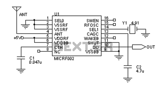
Early transmitters using LC oscillators experience significant frequency drift. The introduction of Surface Acoustic Wave (SAW) devices addresses this issue, providing substantial frequency stability comparable to crystals. These devices can achieve fundamental frequencies in the hundreds of megahertz or...
Stick the metal probes into a freshly watered plant and adjust R5 for a mid-scale meter deflection. The meter will monitor the soil wetness and the meter will indicate whether it is too moist or too dry. This circuit...
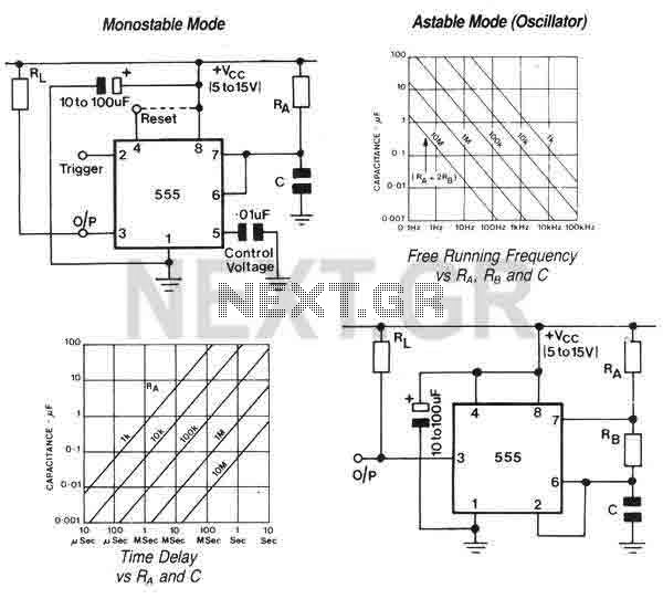
The 555 is a highly stable device for generating accurate time delays or oscillation. Additional terminals are provided for triggering or resetting if desired. In the time delay (monostable) mode of operation, the time is precisely controlled by one...
The tool is based on a NE555 (or LM555) timer i.c., wired as an astable multivibrator. The frequency of the multivibrator is determined by the value of the unknown capacitor Cx. The circuit can be fed by a small...
This power supply is based on the 7805 IC regulator, which provides a regulated output voltage ranging from 5 V to 15 V DC, adjustable by a preset resistor. The maximum output current of this power supply is 350...
I am attempting to construct a Hartley oscillator using a bypassed common emitter configuration. The goal is to achieve oscillation at a frequency of 200 kHz with a peak-to-peak voltage of 2 V, utilizing a BC547B transistor. The Hartley oscillator...