
Voltmeter Ammeter
The voltmeter ammeter circuit utilizes a microcontroller (PIC16F876A) to process analog signals and display the results on an LCD. The resolution of the voltage and current measurements is optimized for a wide range of applications, making it suitable for various electronic projects. The calibration feature enhances the accuracy of measurements, allowing for adjustments based on specific requirements.
The circuit design includes essential components such as a 0.47 Ohm shunt resistor for current sensing, which is critical for accurate current measurement. The inclusion of metal film resistors ensures low tolerance and high precision, which is vital for applications requiring reliable data. The use of a compact PCB layout minimizes space requirements, making it ideal for integration into different electronic systems.
The power consumption of the circuit is optimized to ensure that it can operate efficiently without excessive energy draw. The ability to turn off the LCD backlight further enhances its efficiency, allowing users to conserve power when the display is not needed.
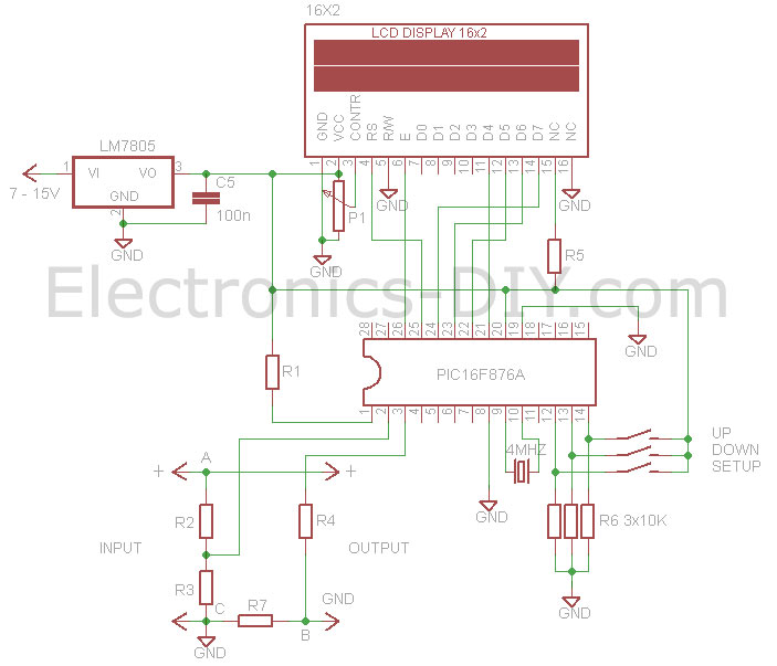
The calibration process is user-friendly, requiring simple interactions with tactile buttons. This accessibility allows users to maintain the accuracy of their measurements over time, making the voltmeter ammeter a versatile tool for both amateur and professional electronics enthusiasts. The retention of calibration settings in EEPROM ensures that the device remains ready for immediate use after power interruptions, further enhancing its practicality in laboratory and field applications.This Voltmeter Ammeter was designed to measure output voltage of 0-70V / 0-500V with 100mV resolution and 0-10A or more current with 10mA resolution. It is a perfect addition to any DIY laboratory power supply, battery chargers and other electronic projects where voltage and current consumption must be monitored.
Thanks to added calibration via SE TUP, UP & DOWN buttons it is now possible to calibrate the meter to measure voltage that is higher than 70V and current that is greater than 10A. The heart of the Voltmeter Ammeter is PIC16F876A microcontroller with built-in analog to digital converters (ADC) and 2x16 green / blue backlighted LCD display.
Voltmeter Ammeter uses very few external components making it possible to fit this handy meter on a small PCB. The meter provides exeptionally accurate readings due to buit-in software based calibration and the use of 1% metal film resistors.
It needs only one supply voltage that can be acquired directly from the main power supply. Entire voltmeter consumes only 10mA with LCD backlight turned on and 3mA with the backlight tuned off. LCD backlight can be turned off by disconnecting 10 Ohm resistor from the LCD display. Current sense 0. 47 Ohm shunt resistor is connected in series with load at the negative voltage rail and is passed to microcontroller chip through 100K resistor.
Additionally the Voltmeter Ammeter can be easlily calibrated by temporaily connecting three (SETUP, UP & DOWN) tactile buttons or even a piece of wire to C1, C2 and C3 PIC16F876 microcontroller ports. To enter the calibration setup mode make sure the meter is powered off. Press and hold the SETUP button for two seconds while powering the meter until "Setup Mode" message is displayed on LCD display.
After "Setup Mode" message disappears we will be calibrating the voltage readings and real time voltage reading will be displayed on the display. Connect the highest voltage to Input that you will be normally measuring then connect the commercial multimeter to input as well.
We will be matching the voltage of PIC voltmeter with the commercial multimeter. Use UP & DOWN buttons to match the voltage on both devices. Once the voltage is matched press the SETUP button to start calibrating current readings. You can lower the voltage now and connect a load from 500mA to axpoximately 2A in series with commercial multimeter to Output of PIC multimeter. Again, we will be matching the current redings on both meters. Finally press the SETUP button again and calibrating settings will be saved in PIC16F876 microcontroller`s non-volatile EEPROM memory.
Calibration process is now completed. EEPROM memory is retained even if the power supply is disconnected. Calibration only needs to be performed once. If you ever need to change the calibration settings again you can do so be following the calibration steps. The PIC multimeter is now ready to be used in the power supply or any other project of your choice. 🔗 External reference
Related Circuits
The sprite, which is experiencing an additional electrical load from an electric cooling fan, is barely maintaining battery charge. To address this issue, an electronic voltage regulator is planned; however, monitoring the charging process is essential before making any...
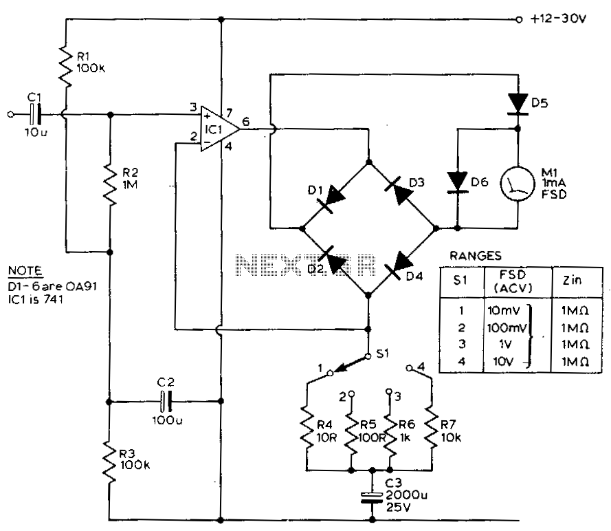
This circuit exhibits a flat frequency response from 8 Hz to 50 kHz, maintaining a -3 dB level at the 10 mV range. Furthermore, while the upper frequency limit remains consistent across less sensitive ranges, the lower frequency limit...
The CA081 and CA3140 BiMOS operational amplifiers provide minimal loading on the circuits being measured. The wide bandwidth and high slew rate of the CA081 enable the meter to operate at frequencies up to 0.5 MHz. The CA081 and CA3140...
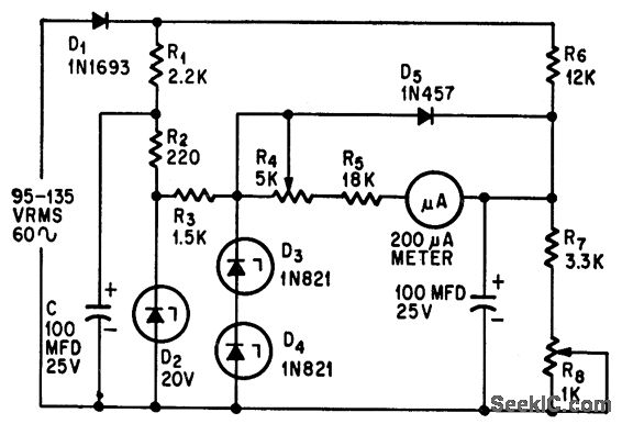
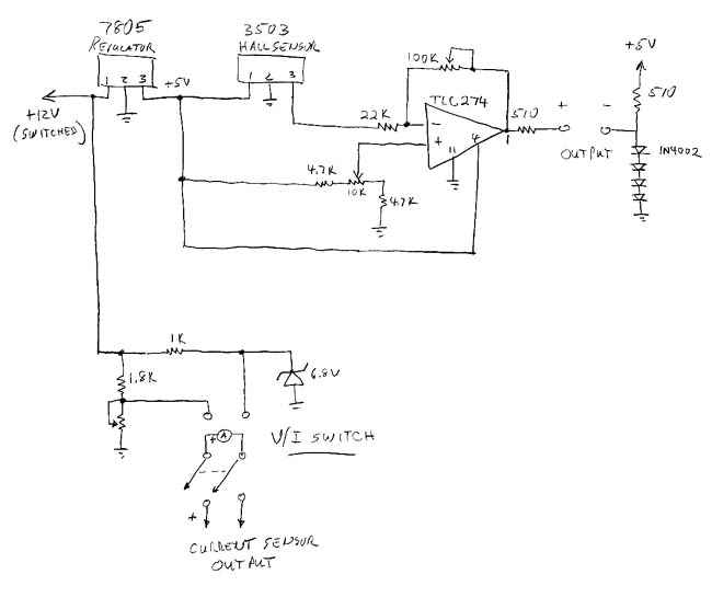
This circuit measures alternating current (AC) voltages in the range of 95 to 135 volts with an accuracy of 0.6%, utilizing a standard meter that has a 2% accuracy rating. The circuit employs Zener diodes to provide a stable...
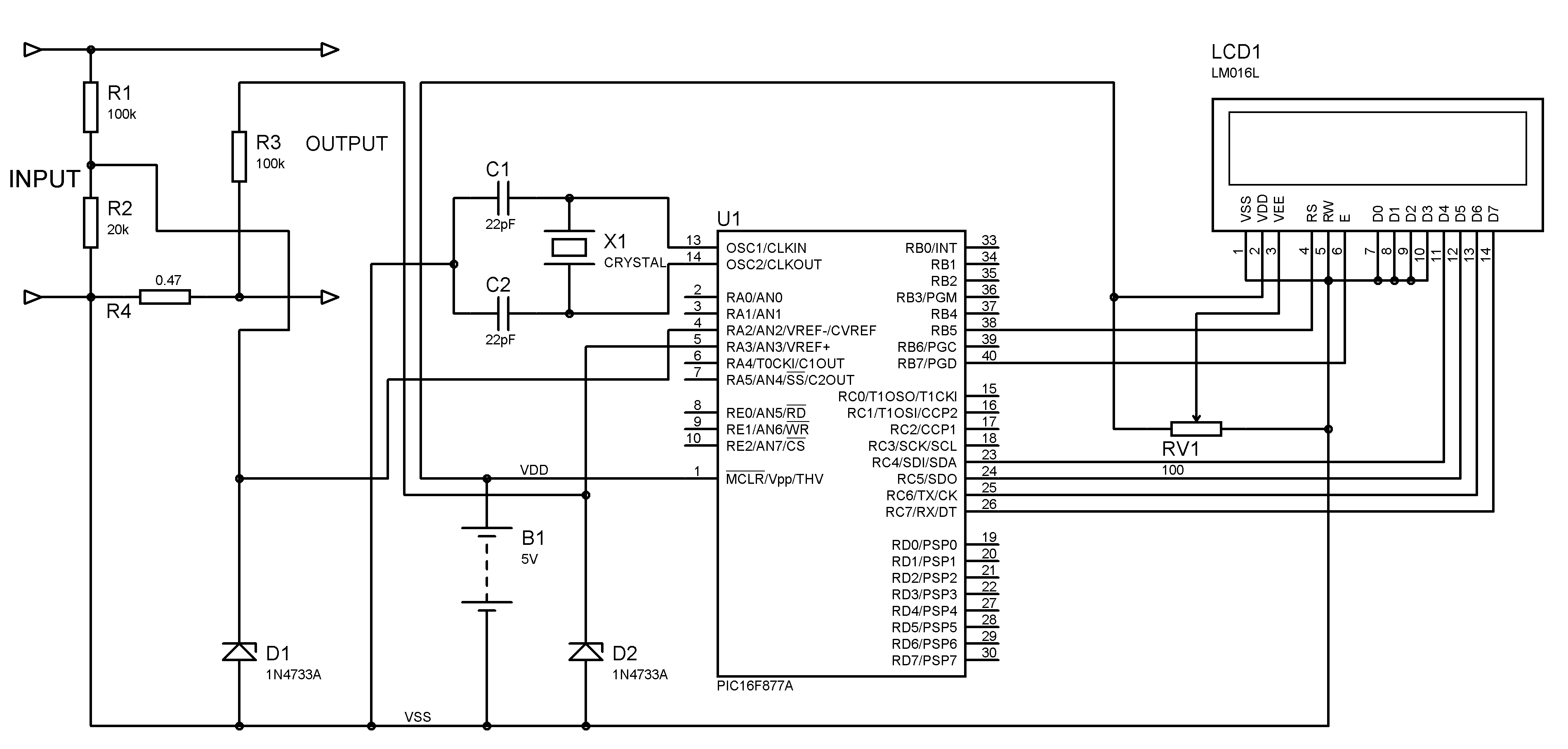
A voltmeter and ammeter can be constructed using a PIC microcontroller equipped with an Analog to Digital Converter (ADC). The project utilizes the PIC16F877A microcontroller, with results displayed on an LCD. This microcontroller is sufficient for testing purposes. For...
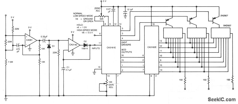
The input stage of this voltmeter circuit utilizes an operational amplifier and diode feedback to create a linear peak value rectifier circuit. A partial pressure isolation through resistors R1 and R2 directs the signal to a dual multi-channel BCD...