
voltmeter ammeter pic

The circuit design for the voltmeter and ammeter using the PIC16F877A microcontroller is a practical application of embedded systems in measurement technology. The microcontroller’s ADC capability allows for precise voltage and current measurements, making it suitable for various testing and experimental setups. The use of a voltage divider enables the measurement of higher voltages (up to 30V) while ensuring that the input to the microcontroller remains within the safe operating range of 0-5V. This is achieved by selecting appropriate resistor values in the voltage divider configuration.
The current measurement aspect of the circuit employs a low-value resistor (1 ohm) to minimize power loss while still providing a measurable voltage drop. The additional 47-ohm resistor serves as a current sensing element, and the feedback mechanism through the 100k ohm resistor ensures that accurate current readings are maintained.
The inclusion of a Zener diode provides an essential safeguard against voltage spikes that could damage the microcontroller, ensuring the longevity and reliability of the circuit. The code structure demonstrates a straightforward approach to reading ADC values and converting them for display, which is vital for user interaction and data interpretation.
In terms of functionality, the circuit can be expanded to include features such as data logging or wireless transmission of measurements, depending on the additional components integrated into the design. The flexibility of the PIC microcontroller allows for future enhancements, making this project a solid foundation for more advanced measurement systems. The LCD display serves as an effective interface for users to visualize real-time measurements, enhancing the usability of the device.
Overall, this design illustrates the intersection of hardware and software in creating an effective measurement tool, showcasing the capabilities of microcontrollers in practical applications.Voltmeter and Ammeter can be easily made using PIC Microcontroller having ADC (Analog to Digital Converter). I am using PIC16F877A and the result is displayed on an LCD Display. PIC16F877A is enough if you do this project only for testing purposes. I suggest to use PIC with low pin numbers and multiplexed 7 segment display if you wish to use thisas your measuring instrument. ADC module of PIC Microcontroller converts the Signals on its analog pin to 10 bit binary data and it hasG‚software selectable high and low voltage reference input to some combination of VDD, VSS, RA2 and RA3. The analog input to PIC is limited to VSS and VDD voltages (0 5V) of PIC. This circuit is designed to measure 0 to 30V. So we will map 0 to 30V to 0 to 5V by using a voltage divider. Current through a circuit can be measured by introducing G‚a 1 ohm resistor and measuring the voltageG‚acrossG‚it.
To minimize the path resistance we will use. 47 ohm special resistor with fuse (shown in figure) and current is calculated. Voltage and Current Sampling circuit is shown below. The voltage across. 47 ohm resistor is also feedback to the analog pin RA3 via 100K ohm resistor. 5. 1V Zener Diode is added in parallel to these analog input pins to protect PIC from over voltages. v = ADC_Read(2); // ADC value of channel 2 (voltage) i = ADC_Read(3); // ADC value of channel 3 (current) V = v*4. 89; // Converting ADC value to mV I = i*4. 89; // Converting ADC value to mV To display the results in LCD Display we need to convert these readings into string, we use the user defined function look() for it.
It converts eachG‚digitG‚in the reading to corresponding character (see the source code). Yes it is possible Apply a known voltage to the unknown resistor and find the current through that resistor . Then we can easily calculate the unknown resistor . can i also use the Voltage Divider principle for that like in your circuit. sir with your permission can i use your schematic diagram up there to build my digital ohmmeter. so you mean to say i will use 5v lower 4v 3. 5v sir can you help me how to declare it. or how can i deal with it in the complier(mikroc ). thank you sir! I think it is better to use Wheatstone bridge to find unknown resistance. In this case you need`nt change the +Vref, instead of you can change the known resistors in the Wheatstone bridge according to the range of resistances you want to measure .
Connect unknown resistance in series with a known resistance You may change the known resistance according to the range of Unknown resistance to be measured. volt[0] = look(v/10000);G‚ G‚ G‚ G‚volt[1] = look(v/1000)%10);G‚ G‚ G‚ G‚volt[3] = look(v/100)%10);G‚ G‚ G‚ G‚Lcd_Out(1, 1, Voltage = );G‚ G‚ G‚ G‚Lcd_Out(1, 11, volt);G‚ G‚ G‚ G‚Lcd_Out(1, 16, V ); I use those steps for converting integer to string to be displayed in the LCD .
You needn`t bother about it use inbuilt functions of mikroC such as FloatToStr(), IntToStr() // LCD module connectionsG‚sbit LCD_RS at RC4_bit;G‚sbit LCD_EN at RC5_bit;G‚sbit LCD_D4 at RC0_bit;G‚sbit LCD_D5 at RC1_bit;G‚sbit LCD_D6 at RC2_bit;G‚sbit LCD_D7 at RC3_bit;G‚sbit LCD_RS_Direction at TRISC4_bit;G‚sbit LCD_EN_Direction at TRISC5_bit;G‚sbit LCD_D4_Direction at TRISC0_bit;G‚sbit LCD_D5_Direction at TRISC1_bit;G‚sbit LCD_D6_Direction at TRISC2_bit;G‚sbit LCD_D7_Direction at TRISC3_bit;// End LCD module connections// Define Messages void main() {G‚char message1[] = DIGITAL OHMMETER ;G‚char *temp = 0000000 ³;G‚unsigned int v, R1, R2, VCC;G‚ TRISC = 0; // PORTC All OutputsG‚ TRISA = 0b000011; // PORTA All Outputs, Except RA3 and RA2G‚G‚G‚ Lcd_Init(); G‚ G‚ G‚ G‚ G‚ G‚ G‚ G‚ G‚ G‚ G‚// Initialize LCDG‚ Lcd_Cmd(_LCD_CLEAR); G‚ G‚ G‚ G‚ G‚ G‚ // CLEAR displayG‚ Lcd_Cmd(_LCD_CURSOR_OFF); G‚ G‚ G‚ G‚// Cursor offG‚ Lcd_Out(1, 1, message1); G‚ G‚ G‚ G‚ G‚ // Write message1 in 1st rowG‚ do {G‚ ADCON1 = 0G—00;G‚ VCC=5000;G‚ R1=10000;G‚ v = ADC_Read(1);G‚ R2 🔗 External reference
Related Circuits
The WWVB signal is broadcast as a 60 kHz carrier that is AM modulated with a time code frame that is updated once per minute. The data rate is one bit per second. Along with time code information, the...
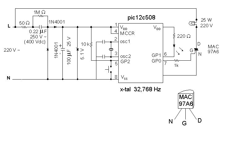
Introduction It is time for the 8-pin microcontroller Microchip PIC12C508, the SAVER V3.2, a new design of a device that controls a night light by turning it on and off. The SAVER V3.2 utilizes the Microchip PIC12C508 microcontroller, which features...
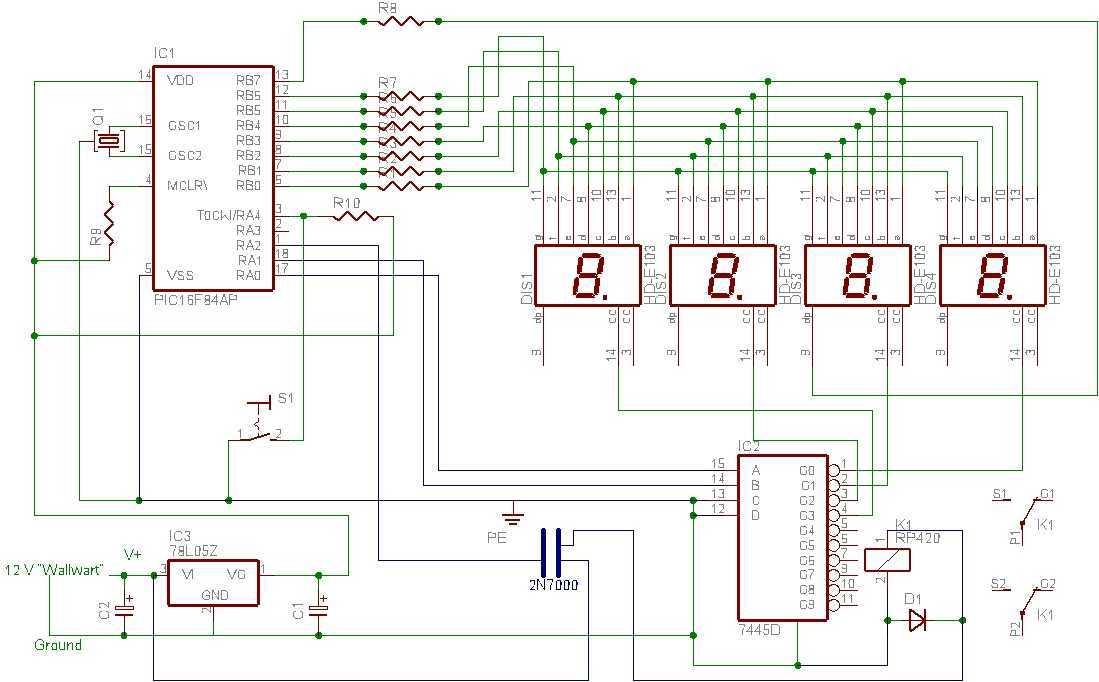
I tried to design a timer that would do everything it needed to do but with the smallest number of pieces and simplest mode of operation. It only needs the PIC, a four digit LED display, one other IC,...
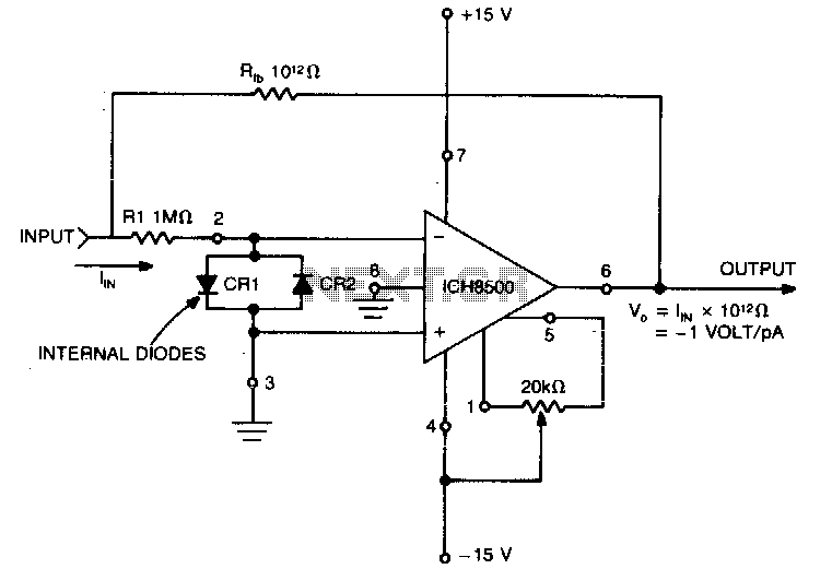
A highly sensitive picoammeter (−1 V/pA) utilizes an amplifier configured in the inverting or current summing mode. It is crucial to eliminate stray currents from entering the current summing mode. The circuit stabilizes to within 1% of its final...
This circuit was formed to create a wireless alarm from a normal magnetic contact. By fixing the magnet to the leaf of a door, or swing of a drawer, it is easy to reveal the opening. To transmit the...
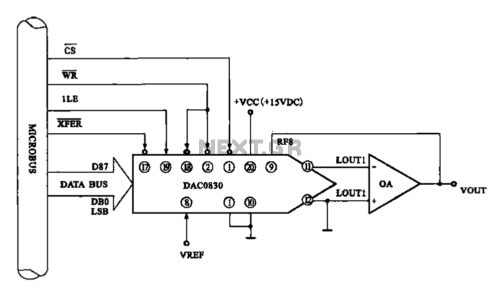
Figure 8 illustrates a typical digital-to-analog (D/A) conversion circuit that utilizes the DAC0830/DAC0832 chip. The microprocessor outputs an 8-bit digital signal, which is converted into an analog signal. The D/A conversion circuit depicted employs the DAC0830/DAC0832, which is a dual...