
vu meter circuit
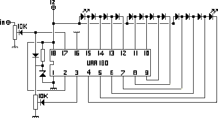
The NL3ASD schematic pages feature a comprehensive design for a LED VU meter that employs the UAA180 IC, known for its audio signal processing capabilities. The UAA180 is specifically designed to drive LED indicators based on the amplitude of audio signals, making it suitable for visualizing audio levels in various applications.
The schematic typically includes a power supply section, which may consist of a voltage regulator to ensure stable operation of the UAA180. The input section connects to an audio source, where the audio signal is fed into the UAA180 for processing. The IC's internal circuitry analyzes the incoming audio signal and generates control signals for the LED drivers.
The output section of the circuit is designed to drive multiple LEDs arranged in a bar graph format or a single LED that varies in brightness according to the audio level. The schematic may also incorporate resistors to limit current to the LEDs, ensuring they operate within safe parameters. Capacitors may be included for filtering to smooth out any noise in the power supply or audio signal.
Overall, the design emphasizes clarity and functionality, allowing for easy interpretation and implementation in various audio applications, such as mixers, amplifiers, or standalone audio level indicators. The schematic serves as a valuable resource for engineers and hobbyists interested in constructing their own LED VU meters.The NL3ASD Schematic Pages - Here Can You Find The Schematics Of A Schematic Of A LED VU Meter With The UAA180.. 🔗 External reference
Related Circuits
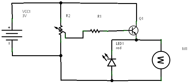
The circuit is connected in parallel with the output of a power amplifier and provides the signal level from the output. By adjusting the resistance R1 in the input circuit, the power indication can be adapted to the resistance...
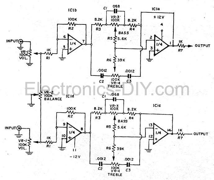
This simple tone control (bass and treble control) can be utilized in various audio applications. It can be integrated into amplifiers, function as a standalone control module, or even be incorporated into new and innovative instruments. The circuit employs...
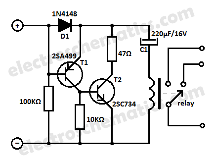
This low current relay circuit is designed for use in battery-operated electronic devices. Its operating current is in microamperes (µA). This is achieved by using a bistable relay and incorporating additional components to enable the relay to function like...
In a prior post titled "Timing is Everything," the application of PWM (Pulse Width Modulation) signals for controlling devices such as LEDs was discussed. This technique is particularly beneficial when working with digital devices, including microchips and microcontrollers, which...
A simple electronic lock circuit that requires minimal materials for its construction. This electronic lock circuit is designed for ease of assembly and functionality, making it suitable for various applications where secure access control is necessary. The circuit typically comprises...
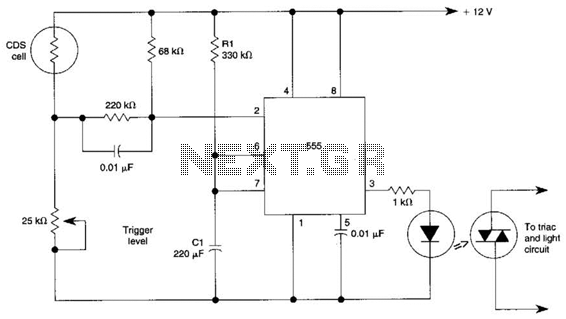
This circuit can control the on/off cycle of a light using a CDS photocell and turn it off after a preset period. The light can only be activated when the CDS cell is in darkness, and it remains on...