
VU Meter with UAA180

The Siemens UAA180 is an integrated circuit specifically designed for driving LED displays, making it ideal for applications such as audio level indicators. This circuit utilizes the UAA180 to control multiple LEDs in a light band display, providing a visual representation of audio signal levels. The UAA180 operates by adjusting the current flowing through the LEDs, allowing for precise brightness control based on the input audio signal.
The circuit typically includes several key components: the UAA180 IC, resistors to limit current through the LEDs, and capacitors for stability and filtering. The audio signal is fed into the UAA180, which processes the signal and converts it into a corresponding output that drives the LEDs. The design may also incorporate additional features such as a potentiometer for adjusting sensitivity, ensuring that the display can be calibrated to different audio signal levels.
In practice, the circuit can be configured to illuminate a series of LEDs in a graduated manner, providing a clear visual representation of the audio signal's amplitude. This is particularly useful in audio equipment, where visual feedback is essential for monitoring levels and ensuring optimal performance. The UAA180's ability to handle varying input signals while maintaining consistent LED brightness makes it a valuable component in audio level display applications.
Overall, the design of this circuit emphasizes efficiency and accuracy in displaying audio signal levels through LED indicators, leveraging the capabilities of the UAA180 to create a reliable and effective tool for audio signal monitoring.The circuit was designed based on the operation of Siemens UAA180 as it functions as a LED driver for light band displays for measuring the level of audio signals. 🔗 External reference
Related Circuits
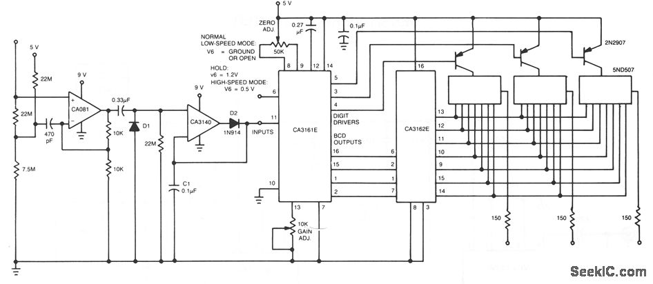
The CA081 and CA3140 BiMOS operational amplifiers provide minimal loading on the circuits being measured. The wide bandwidth and high slew rate of the CA081 enable the meter to operate at frequencies up to 0.5 MHz. The CA081 and CA3140...
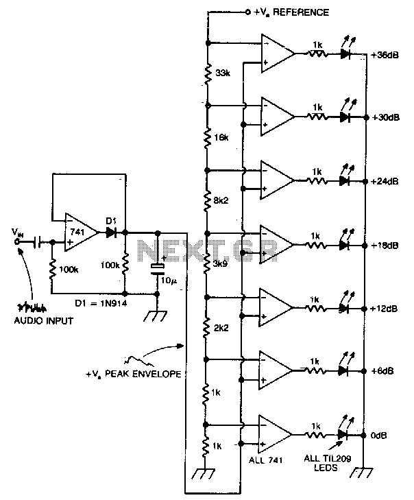
A vertical column of LEDs is configured so that as the audio signal level rises, an increasing number of LEDs illuminate. The LEDs are arranged in increments of 6 dB. The circuit features a fast response time and a...
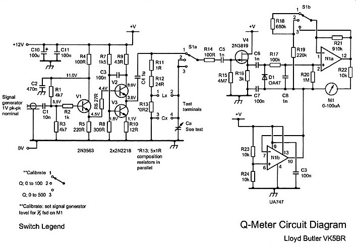
The Q meter has been an essential piece of equipment for laboratories engaged in the testing of radio frequency circuits. In modern laboratories, the Q meter has been largely replaced by more advanced and costly impedance measuring devices, making...

The magnetometer was relocated to an outdoor site, and a specialized enclosure was constructed. An accessory temperature controller was incorporated to ensure a constant temperature, and a digital link was established to transmit the recorded data back to the...
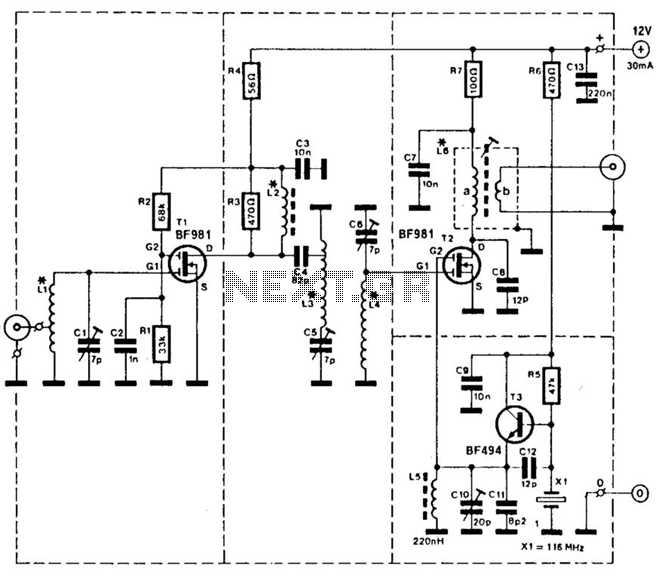
This converter allows a receiver that operates within the frequency range of 28 to 32 MHz to receive signals from the 144 to 148 MHz amateur band. It utilizes a BF981 dual-gate MOSFET to provide RF gain, which is...
A series of shunts and multipliers selected by a switch can be utilized in conjunction with a single basic meter to create a multirange instrument, commonly referred to as a multimeter. This device is capable of measuring voltage, current,...