
Q Meter
The Q meter is a vital instrument for assessing the quality factor of inductors and capacitors within radio frequency applications. Its operational principles hinge on the relationship between reactance and resistance in tuned circuits, providing insights into circuit performance and efficiency. The construction of a basic Q meter involves careful selection of components, such as a high-quality variable tuning capacitor and a tunable signal source, to ensure accurate measurements. The series resistor must be chosen to minimize its impact on the overall circuit, allowing for precise readings of both injected and output voltages. Calibration of the meter is critical to ensure reliable Q factor readings, which can inform adjustments in circuit design and component selection for optimal performance. The versatility of the Q meter makes it an indispensable tool for both amateur radio enthusiasts and professionals in the field, facilitating a deeper understanding of circuit dynamics and enhancing the efficacy of radio frequency applications.The Q meter has been an essential piece of equipment for laboratories engaged in the testing of radio frequency circuits. In modem laboratories, the Q meter has been largely replaced by more exotic (and more expensive) impedance measuring devices and today, it is difficult to find a manufacturer who still makes a Q meter.
For the r adio amateur, the Q meter is still a very useful piece of test equipment and the writer has given some thought to how a simple Q meter could be made for the radio shack. For those who are unfamiliar with this type of instrument, a few introductory notes on the definition of Q and the measurement of Q, are included.
The Q factor or quality factor of an inductance is commonly expressed as the ratio of its series reactance to its series resistance. We can also express the Q factor of a capacitance as the ratio of its series reactance to its series resistance although capacitors are generally specified by the D or dissipation factor which is the reciprocal of Q.
A tuned circuit, at resonance, is considered to have a Q factor. In this case, Q is equal to the ratio of either the inductive reactance, or the capacitive reactance, to the total series loss resistance in the tuned circuit. The greater the loss resistance and the lower the Q, the greater the power lost on each cycle of oscillation in the tuned circuit and hence the greater the power needed to maintain oscillation.
Sometimes we talk of loaded Q (such as in transmitter tank circuits) and, in this case, resistance for calculation of Q is the unloaded tuned circuit series resistance plus the additional loss resistance reflected in series into the circuit from its coupled load. There are other ways of expressing Q factor. It can be expressed approximately as the ratio of equivalent shunt resistance to either the inductive or the capacitive reactance.
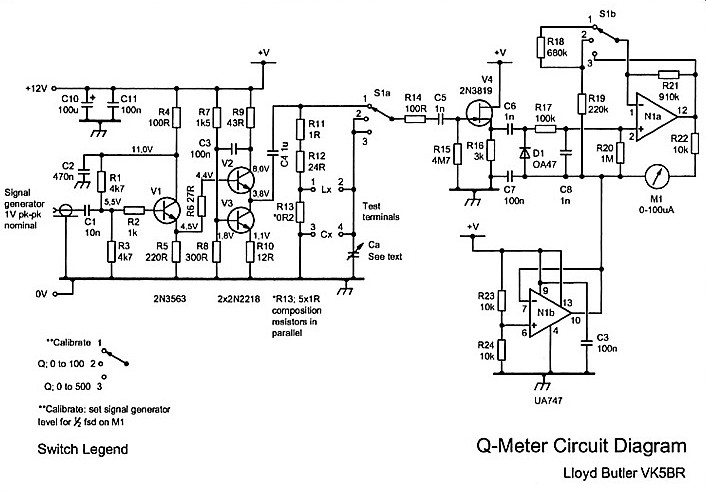
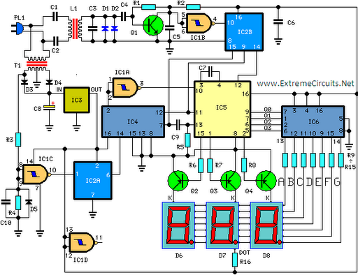
Series loss resistance can be converted to an equivalent shunt resistance using the following formula: Finally, Q factor of a resonant circuit is equal to its voltage magnification factor and Q can also be expressed as the ratio of voltage developed across its reactive elements to the voltage injected in series with the circuit to produce the developed voltage. To measure Q factor, Q meters make use of this principle. A basic Q meter is shown in Figure 1. Terminals are provided to connect the inductance (Lx) to be measured and this is resonated by a variable tuning capacitor (C).
Terminals are also provided to add capacitance (Cx), if required. The tuned circuit is excited from a tunable signal source which develops voltage across a resistor in series with the tuned circuit. The resistor must have a resistance small compared to the loss resistance of the components to be measured so that its value can be ignored.
A resistance of a mere fraction of an ohm is necessary. Metering is provided to measure the AC injection voltage across the series resistor and the AC output voltage across the terminals of the tuning capacitor. The output measurement must be a high input impedance circuit to prevent loading of the tuned circuit by the metering circuit.
Q is measured by adjusting the source frequency and/or the tuning capacitor for a peak in output voltage corresponding to resonance. Q factor is calculated as the ratio of output voltage measured across the tuned circuit to that injected into it.
In practice, the signal source level is generally set for a calibrate point on the meter which measures injected voltage and Q is directly read from calibration on the meter which measures output voltage. The Q meter can be used for many purposes. As the name implies, it can measure Q and is generally used to check the Q factor of inductors. As the internal tuning capacitor has an air dielectric its loss resistance is negligible compared to that of any inductor and hence the Q measured is that of the inductor.
The value of Q varies considerab 🔗 External reference
Related Circuits
Unlike a standard voltmeter, an oscilloscope typically has one input terminal (GND) connected to ground through the mains lead. In specific situations... An oscilloscope is a vital instrument in electronics for visualizing voltage signals over time. It provides a graphical...
A UHF indicator, or wavemeter, is a device that measures frequencies and determines the resonance frequency of an LC circuit. This device operates without the need for radiation. The oscillator is constructed using transistors T1 and T2 (two BF494),...
T-121 temperature sensor electronic thermometer circuit diagram shown below The T-121 temperature sensor circuit is designed to measure and display temperature readings accurately. The circuit typically consists of a temperature sensor, such as the T-121, which converts temperature variations into...
This circuit is designed for precise measurement of temperature in degrees Celsius. It features a transmitter section that converts the output voltage from a temperature sensor, which is proportional to the temperature being measured, into frequency. The resulting frequency...
The circuit was designed to create a low-cost frequency meter that will cover the range of 1 Hz to 1 MHz with a digital indication using three 7-segment displays. The frequency meter circuit operates by measuring the frequency of an...

This light meter features an eight-decade range. Bias current compensation enables an input current resolution of better than ±2 pA over a temperature range of 15 °C to 55 °C. The light meter is designed to measure luminous intensity across...