
Pink noise generator circuit mod

The updated schematic incorporates an RF Solutions receiver, which is essential for receiving radio frequency signals. The receiver is typically characterized by its ability to demodulate signals, thereby converting them into usable data. The additional circuitry included in the schematic serves multiple purposes, such as signal amplification, filtering, and conditioning, which are crucial for ensuring that the received signals are clean and free from noise.
Signal amplification is achieved through operational amplifiers (op-amps), which boost the weak signals received by the RF Solutions receiver to levels suitable for further processing. The amplification stage is followed by a filtering section, which may consist of low-pass, high-pass, or band-pass filters designed to eliminate unwanted frequencies and enhance the desired signal.
Moreover, the circuit may include components such as resistors, capacitors, and inductors, which are strategically placed to form RC or LC networks that define the frequency response of the filters. Additionally, the schematic may feature a microcontroller or digital signal processor (DSP) to interpret the demodulated signals, allowing for further processing, analysis, or communication with other devices.
Power supply considerations are also critical in this design. The schematic may include voltage regulators to ensure stable operation of the receiver and associated circuitry. Proper grounding techniques and decoupling capacitors are essential to minimize electromagnetic interference (EMI) and ensure reliable performance.
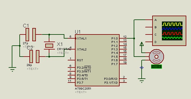
Overall, this updated schematic represents a comprehensive approach to RF signal reception, with attention to detail in both the receiver design and the supporting circuitry, ensuring optimal performance in various applications.Here`s an updated schematic with the RF Solutions receiver and some other small additions. There`s a lot of extra circuitry to deal with the signals.. 🔗 External reference
Related Circuits
What exactly is a multivibrator? I suppose one definition would be 'a circuit which has several states'. This will do for now, it's quite loose so leaves plenty to the imagination! Conventional multivibrators have only two stages and come...
A program is available to control a simple servo motor in both directions. This program has been tested and can be shared for others to benefit from it. It allows the servo motor to rotate in both clockwise and...
The purpose of this circuit is to animate shop windows using a capacitive sensor positioned behind a postcard-like banner. The card is placed against the glass inside the shop window, allowing visitors to activate the relay by placing their...
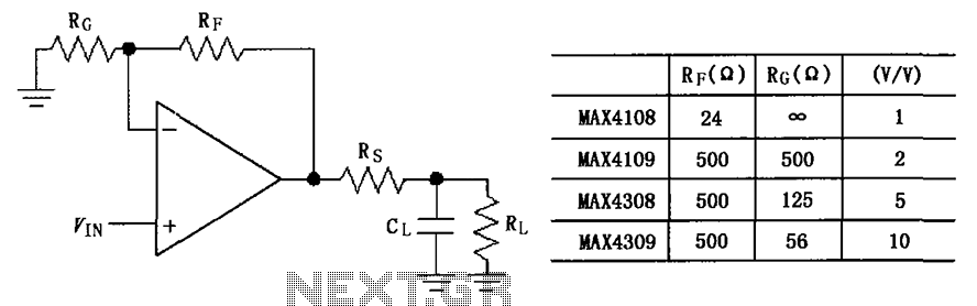
The circuit depicted in the figure employs the MAX4108/4109/4308/4309 operational amplifiers with a capacitive load driving circuit isolation resistor (Rs). While the MAX4108/4109/4308/4309 exhibits excellent AC characteristics, it is not optimized for driving high-load electrical resistances. A significant reactive...
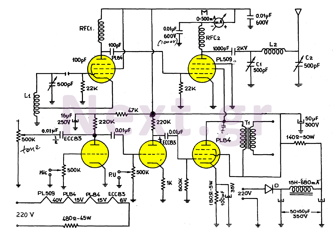
The simplicity of this transmitter, combined with its high performance, makes it particularly interesting. It has an output power of approximately 30 W, and under normal conditions, with the appropriate antenna and handling, it can achieve a range of...
This signal generator is designed for the realignment of radio receivers. The unit is inexpensive and relatively simple but adequately serves its intended purpose. However, the output is not a pure sine wave, which may make it unsuitable for...