
W3HWJ Radio Receiver Projects
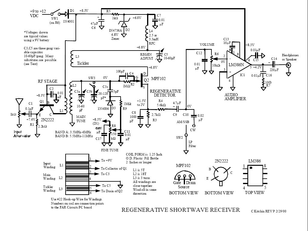
This project illustrates the fundamentals of regenerative radio design, emphasizing the importance of component selection and layout in achieving optimal performance. The use of a simple integrated circuit allows for a compact and efficient design, while the innovative use of an LED as a voltage regulator showcases creative problem-solving in circuit design. The challenges faced in this project, such as interference and tuning difficulties, highlight the need for careful consideration of circuit parameters and environmental factors in radio communications. The learning experience gained from PCB design and construction further enhances the understanding of electronic circuit design principles, making this a valuable endeavor for both hobbyists and professionals in the field. The attention to detail in housing the project and labeling controls also reflects best practices in electronic design, contributing to user-friendly interfaces and overall project aesthetics.The logical first choice was to start out with simple regenerative circuits. Just one or two transistors and maybe a simple audio amplifier using one integrated circuit. I already have a few simple tube radios that I bought at flea markets, so I will defer any tube projects for a while yet. Charles Kitchin has written many articles about regen radios for QST and other hobby magazines. I like his approach to design and have had good luck with his circuits. The first attempt at a "Kitchin" used a printed circuit board that I bought from Far Circuits. This was an excellent learning tool and prompted me to continue experimenting and changing the design and the circuit board. To house this project, I "re-purposed" a metal container that originally contained Christmas cookies.
After drilling the mounting holes for all the controls, I used a bit of steel wool to create a matte finish, cleaned with mineral spirits, and then spray painted. The labels for the controls were made with a Brother P-touch labeler. Thanks to Dave Schmarder, N2DS, for getting me interested in the Brother. It makes a nice laminated label that is good-looking, sturdy, and solidly adherent. By changing the plug-in coil, I can cover 3. 5 to over 10 MHz. It`s a bit difficult to copy SSB signals as the detector is not super stable, but it works well enough!
I made a few mistakes in this version, such as mounting the speaker on the side of the case. It needs to be on the front or the top cover to direct sound toward the listener. Also, using a large value main tuning capacitor proved to be a problem, even though I used an 8:1 reduction dial. The vari-cap "fine tuning" is definitely needed to copy SSB successfully! Designing and making your own pc board is challenging and educational. I learned about ExpressPCB software, blue Press `n Peel transfer film, and using peroxide and muriatic acid to etch boards.
I also found that the toner used by Brother laser printers doesn`t work as well as HP toner for making etching masks using Press `n Peel film. PVC plumbing pipe and fittings make good coil forms when used in conjunction with bases salvaged from defective radio tubes.
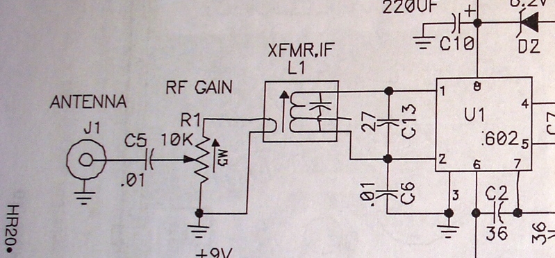
This design uses a 6-pin tube base. At most ham swap meets, I can buy dead 6-pin tubes for 25 cents. This simple 3-pin integrated circuit has always been interesting to me. Invented by Ferranti in the UK about 4 decades ago, it was aimed at very simple AM radios that were made in places like Hong Kong. It uses only a single 1. 5V battery and a minimum of external components. With a minimum number of parts, I was amazed that I could receive KCBS (740 KHz. ) from San Francisco (60 miles) without any external antenna. My chief problem was that KSRO, about 3 miles away on 1350 KHz. , came blasting through and covered half the available band! The circuit is sensitive, but not very selective. My interesting innovation for this circuit was to replace the variable 47K resistor with an LED used as a voltage regulator.
The forward voltage of the LED keeps pin 1 at about 1. 7 Volts. I later learned that this is a bit high and 1. 2 Volts will work better. 🔗 External reference
Related Circuits
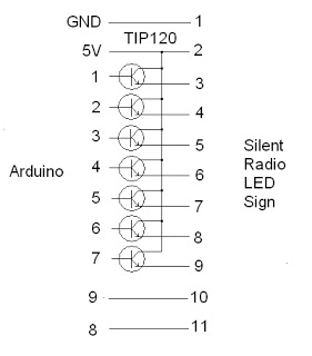
The project addresses a brightness issue with the LED display. The original design using a 4017 counter was ineffective because it lacked the capability to turn off the display while updating the shift registers. Consequently, the decision was made...
The following circuit illustrates the RF block diagram of a GPS receiver. This circuit is based on the MAX2742 integrated circuit. Features include a complete GPS receiver functionality. The GPS receiver RF block diagram utilizing the MAX2742 IC encompasses several...
This technical note focuses on determining the system specifications of a CDMA receiver to establish practical specifications for a low noise amplifier and down converter. The design of a CDMA (Code Division Multiple Access) receiver necessitates a comprehensive understanding of...
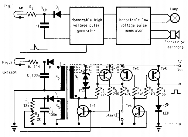
In the absence of radiation, no current is drawn. At normal background radiation levels, the power consumption is extremely low. The instrument may be left on for several months without changing batteries. In this way, the detector is always...
Here is a Tesla coil secondary design: Wind 750 turns of 24-gauge enameled magnet wire onto an 18-inch long piece of 1.9-inch outer-diameter PVC pipe. The large coil has an inductance of approximately 2800 mH and a self-capacitance of...
Direct Conversion Receiver: making friends with the Signetics SA602 IC. Introduction: How simple can it be? If you are a minimalist and like to work with small electronics projects, then you should become acquainted with the SA602 chip. The...