
Zener Oscillator circuits
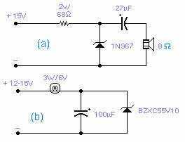
Circuit (a) employs a zener diode as the primary oscillation component, necessitating a careful preparation phase referred to as "cooking." This process involves connecting the zener diode to a constant current generator, allowing for controlled current adjustment. The key operation is to increase the current until the voltage across the zener diode begins to drop, indicating it is nearing its breakdown voltage. After reaching this point, the supply current should be reduced, allowing the zener to stabilize at an elevated temperature. This thermal management is critical for achieving stable oscillation characteristics.
Once the zener is properly conditioned, the voltage can be incrementally increased until oscillation is observed, typically around 1 kHz. It is important to note that once oscillation occurs, further voltage adjustments may be necessary to maintain consistent operation. With the right selection of components, this circuit can achieve oscillation frequencies up to 20 MHz, making it suitable for various high-frequency applications.
Circuit (b), in contrast, operates at significantly lower frequencies, generally between 2 to 5 Hz. The initiation of oscillation in this circuit is highly sensitive to the voltage increase rate, emphasizing the need for gradual voltage adjustments. Additionally, the circuit's performance is influenced by the load, particularly if a lamp is used as part of the oscillation mechanism. It has been observed that higher voltage zeners tend to perform better than their lower voltage counterparts, making the choice of the zener diode crucial for circuit functionality.
The underlying mechanisms driving the oscillations in both circuits remain somewhat enigmatic. For circuit (b), there is a hypothesis suggesting that reversible thermal breakdown may play a role in the oscillation phenomenon. This aspect warrants further investigation to fully understand the operational principles and enhance the reliability of these circuits in practical applications. The specified components are essential for ensuring proper circuit behavior, and deviations from these specifications may lead to unpredictable performance.These two circuits are interesting from an academic point of view. Their practical implementation is rather critical and it is not easy to get steady operation. Circuit (a) requires a "cooked" zener: connect it first to a constant current generator, then increase the current until the voltage across the zener starts to decrease. Reduce the supply current and wait a few minutes until it really warms up. The zener is now ready for the circuit: increase the voltage slowly until it oscillates (1KHz in the circuit shown).
You may need to decrease the voltage once oscillation takes place. With suitable circuit components it will oscillate up to 20MHz. Circuit (b) will oscillate at a very low frequency, normally 2-5Hz, provided the voltage is increased very slowly, loading is critical and you may find that a slightly different lamp will work better. Higher voltage zeners work better than low voltage zeners and the circuits operate only with the specified types.
The reasons for the oscillations are unknown, although, for circuit (b) it is felt that some kind of reversible thermal breakdown is at work. 🔗 External reference
Related Circuits
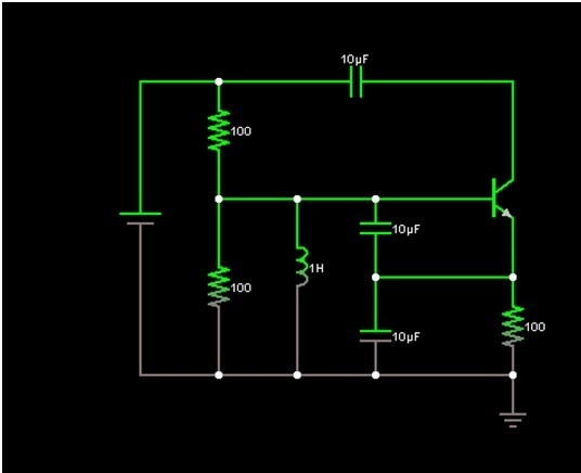
Design a Colpitts oscillator in a common collector configuration using a single BJT. Provide base current to ensure the transistor operates correctly, which can be achieved using a potential divider (between Vcc and ground). It is advisable to use...
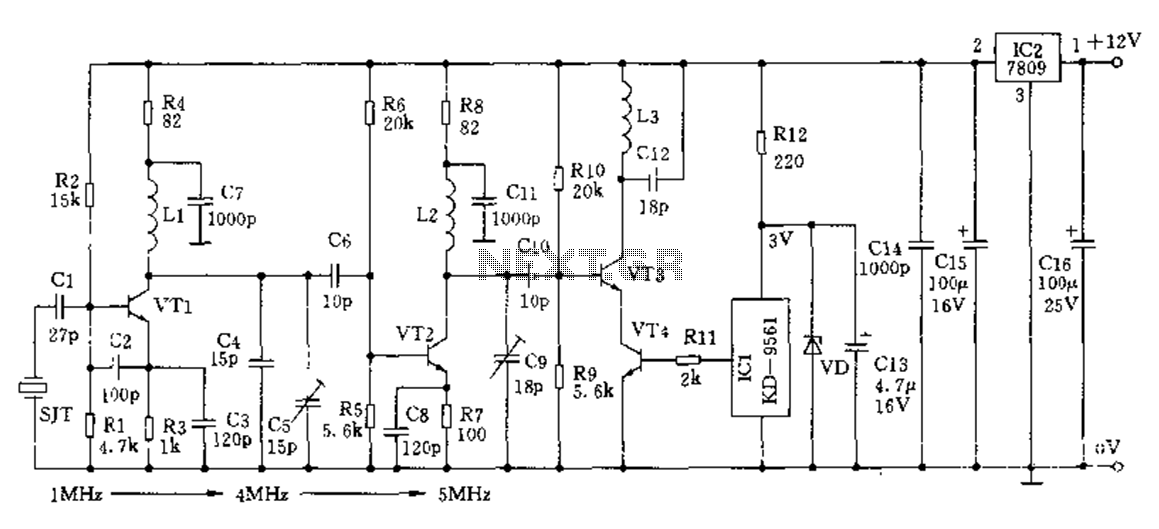
The crystal frequency stabilization of a frequency modulation circuit is illustrated below. The frequency modulation (FM) circuit utilizes crystal frequency stabilization to ensure precise frequency control and stability. This process involves the use of a quartz crystal oscillator, which...
The AM transmitter circuit consists of an audio amplifier and an RF oscillator. The oscillator is constructed around transistor Q1 and its associated components. The tank circuit, which includes inductor L1 and variable capacitor VC1, is tunable from approximately...

This circuit includes an amplifier designed to deliver +10 dBm to an SBL series (Mini-Circuits) or a similar type of doubly-balanced mixer assembly. The circuit parameters are specified for 80 to 90 MHz crystals, although the values of the...
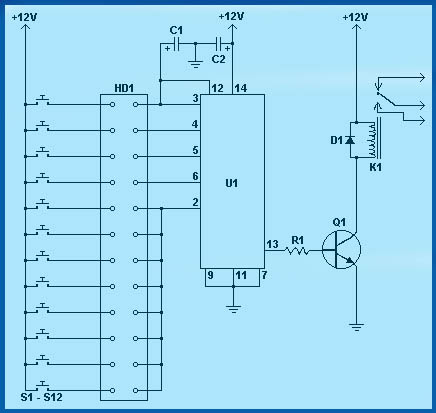
Circuit diagram schematics of electronic keys, electronic locks, digital electronic locks, transistor code locks, and combination electronic locks. The circuit schematics for electronic locking mechanisms encompass a variety of designs tailored to enhance security and convenience in access control systems....
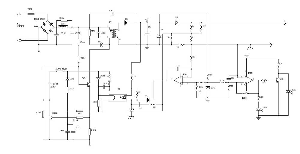
Several schematic drawings of battery charger circuits are provided. These circuits cover 5W to 200W for NiCd, NiMH, Lead-Acid, Li-Ion/Polymer, and LiFePO4 battery packs. The charger circuit files aim to assist users in selecting the appropriate chargers and to...