
Rf-Type Battery Charger Circuit

The described RF charger operates on the principle of inductive coupling, where an alternating magnetic field produced by L2 induces a voltage in the external pickup coil. The use of RF energy is particularly beneficial in applications where contact-based charging methods are impractical or undesirable. The design's reliance on ferrite material enhances the efficiency of energy transfer by providing a high magnetic permeability, which concentrates the magnetic field and reduces losses.
In this configuration, L2 acts as the primary coil, generating an RF field when energized. The external pickup coil, acting as the secondary, captures this energy and converts it into electrical energy through electromagnetic induction. The rectifier connected to the pickup coil is crucial for converting the induced AC voltage into a usable DC voltage suitable for charging the battery.
The choice of wire gauge for the coils is significant; #24 wire for L2 and #30 wire for L3 indicates a balance between resistance and inductance. Thicker wire (like #24) for the primary coil allows for lower resistance and better current handling, while the thinner wire (like #30) for the secondary coil may be sufficient for the lower currents expected during the charging process.
The 1V ferrite rod serves as a structural support for the coils while also enhancing the magnetic coupling between them. The dimensions and material properties of the ferrite rod are critical in optimizing the performance of the charger, as they affect the inductance values and the efficiency of energy transfer.
This wireless charging system can be utilized in various applications, including medical implants, consumer electronics, and other devices where traditional charging methods may be impractical. The absence of physical connectors minimizes wear and tear, reduces maintenance, and enhances the overall reliability of the charging solution. This type of charger couples RF from L2 to an external pickup coil. The pickup coil connects to a rectifier and battery to be charged. This idea is handy because no wire or contacts are required. L2 is 10T #24 wire and L3 is 10T #30 wire. Both coils are mounted on a 1 V ferrite rod. 🔗 External reference
Related Circuits
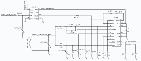
The UC3825 IC, manufactured by Texas Instruments, is a high-speed pulse width modulation (PWM) controller that serves as the central processor for a DC/DC converter control circuit. This circuit primarily consists of three integrated circuits: the UC3825BN, ISO124, and...
Schematic and description of a simple and easy-to-build NiCd and NiMH battery charger circuit that is capable of charging multiple NiCd and NiMH batteries. The circuit for the NiCd and NiMH battery charger is designed to be straightforward, allowing for...
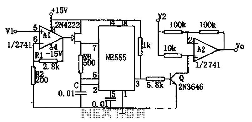
The circuit depicted in the figure consists of a voltage-frequency converter and an amplitude modulator. The input voltage V1, processed by operational amplifier A1, controls the FET 2N4222's internal resistance, which in turn alters the oscillation frequency of the...
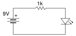
Beginner's Tutorial 1: Building a Circuit on Breadboard - how to build a simple and easy circuit on a breadboard for beginners in electronics. Learn to use an LED and a resistor. This tutorial serves as an introductory guide for...
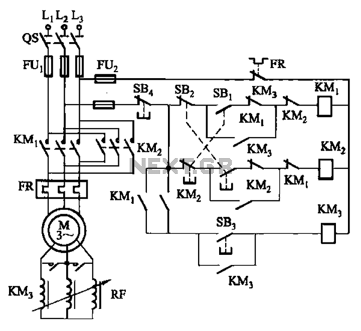
The circuit illustrated in Figure 3-166 employs a button control mechanism. To initiate forward motion, the user presses button SB1, which activates the motor rotor through a frequency-sensitive rheostat (RF). As the motor speed approaches its rated speed, a...
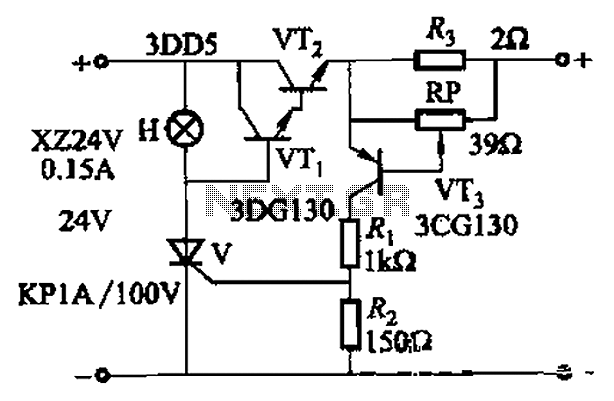
By adjusting Ro or RP, the current setpoint can be modified. The circuit illustrated in Figure 14-98 features overcurrent protection using a thyristor and transistors VTi and VT2, which immediately cut off the power when an overcurrent condition is...
Warning: include(partials/cookie-banner.php): Failed to open stream: Permission denied in /var/www/html/nextgr/view-circuit.php on line 713
Warning: include(): Failed opening 'partials/cookie-banner.php' for inclusion (include_path='.:/usr/share/php') in /var/www/html/nextgr/view-circuit.php on line 713