Water Activated Alarm
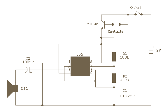
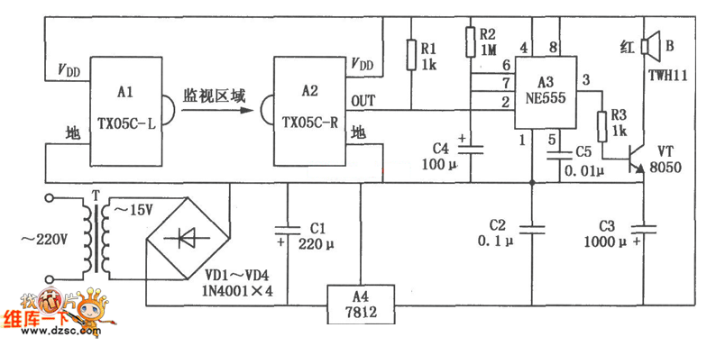
The circuit uses a 555 timer wired as an astable oscillator and powered by the emitter current of the BC109C. Under dry conditions, the transistor will have no bias current and be fully off. As the probes get wet, a small current flows between base and emitter and the transistor switches on. A larger current flows in the collector circuit enabling the 555 oscillator to sound.
The described circuit operates using a 555 timer configured in astable mode, which allows it to generate a continuous square wave output. This configuration is particularly useful for applications requiring audio signals or tone generation, such as alarms or indicators. The 555 timer's frequency and duty cycle can be adjusted by selecting appropriate resistor and capacitor values in the timing network.
The BC109C transistor serves as a switching device in this circuit. It is a general-purpose NPN transistor capable of handling moderate currents, and it is used to control the operation of the 555 timer based on the moisture detected by the probes. In the dry state, the absence of bias current at the base of the BC109C keeps the transistor in the off state, preventing any current from flowing through the collector-emitter path. Consequently, the 555 timer remains inactive, and no sound is produced.
When moisture is detected, the conductivity between the probes increases, allowing a small bias current to flow into the base of the BC109C. This small current is sufficient to turn the transistor on, allowing a larger current to flow from the collector to the emitter. As the transistor activates, it powers the 555 timer, initiating the oscillation process. The output from the 555 timer can then be connected to a speaker or buzzer, producing an audible tone that indicates the presence of moisture.
In terms of component selection, the timing capacitor connected to the 555 timer should be chosen to achieve the desired frequency of oscillation. Additionally, the resistors used in the timing network will determine the duty cycle of the output waveform. Careful consideration of these parameters will ensure optimal performance of the moisture detection circuit.
Overall, this circuit provides a simple yet effective means of moisture detection, utilizing the characteristics of the 555 timer and the BC109C transistor to create an audible alert when wet conditions are present.The circuit uses a 555 timer wired as an astable oscillator and powered by the emitter current of the BC109C. Under dry conditions, the transistor will have no bias current and be fully off. As the probes get wet, a small current flows between base and emitter and the transistor switches on.
A larger current flows in the collector circuit enabling the 555 osillator to sound. 🔗 External reference
