
handheld RF-Powermeter for multiple sensors up to 12 GHz
The DSPM03 design is centered around two types of sensors, each serving a distinct purpose in measuring RF power. The diode sensor is designed to convert RF signals into a corresponding DC voltage, which is then processed by the microcontroller. The diode sensor's characteristics, including its frequency response and linearity, are critical for achieving accurate measurements across a wide frequency range. The thermal power sensor operates on a different principle, utilizing the heat generated by RF power absorption to produce a measurable voltage. This dual-sensor approach allows for enhanced versatility in measurement, accommodating varying RF signal characteristics.
The digital section of the DSPM03 is powered by an Atmel AVR microcontroller, which handles data acquisition through integrated ADCs. The microcontroller also manages the display output, providing real-time feedback to the user regarding RF power levels. The choice of a 4x16 character LCD display facilitates clear and concise visualization of measurement data, including both the calculated RF power and the raw ADC values.
In terms of construction, the DSPM03 is designed to be user-friendly, with a focus on accessibility for hobbyists and professionals alike. The use of standard components, such as the 4x16 LCD display and commonly available resistors and potentiometers, simplifies the assembly process. Detailed schematics and software documentation are provided to assist users in replicating the design accurately.
Calibration of the DSPM03 is an essential step to ensure measurement accuracy. The software's lookup table must be populated with precise values correlating DC voltage levels to RF power measurements. This calibration process may involve testing the device with known RF power levels and adjusting the lookup table accordingly to achieve optimal performance.
In summary, the DSPM03 represents a sophisticated yet accessible solution for RF power measurement, combining innovative sensor technology with robust digital processing capabilities. The integration of both diode and thermal sensors, along with a user-friendly interface, positions the DSPM03 as a valuable tool for both amateur and professional radio enthusiasts.A couple of few years ago I had build a diode-sensor based RF powermeter using a 68HC11 microprocessor. Even before that I had build an analog RF powermeter with thermal power sensor. And I found datasheets of logarithmic amplifiers very interesting, that promised a measurement bandwidth of up to 2.
5GHz. When I had familiarized myself with the Atm el AVR microprocessor family, it was just a logic step to build myself a nice powermeter for all three measurement principles. So I did that and build a very small, battery powered powermeter with external power sensors. I called it UMD, the Universal Measurement Device. It was completely done with tiny surface mount components. Wanna see Click here for a picture. Or here for another picture. Here the UMD is measuring a beacon transmitter with the diode sensor. Unfortunately the device contained a few components that were very had to get (e. g. a mobile phone LCD display) and was so tiny that it was difficult to compare it with my documentation.
I had changed the circuit a couple of times during the development, so I could not guarantee that my schematics were correct. When I was asked by some Belgian radio amateurs to write an article for their annual magazine, I decided to rebuild the circuit on a larger board with wired components and a standard 4x16 character LCD display.
Lets call that version article-breadboard version. The breadboard was laying around for a few month until I decided that I should rather use it to build myself another power meter. Since I already had the UMD with the external sensors, I have included the sensors now in the meter housing.
I had almost never used the log-amp sensor, so I went for a design with only two sensors: a diode sensor and a thermal power sensor. Since it was kind of a third approach I have named this version DSPM03, the Dual Sensor Power Meter 03.
If you want to copy one of my power meters, I strongly recommend to copy the DSPM03. If you are interested in the older design, feel free to have a look at the unsupported files. For the hardware at hardware/ and for the firmware at firmware/. The Powermeter consists of two logic components. One is the digital part, consisting of the processor (including the ADCs), the display and the batteries. The other component is one of different sensors that transform the RF input power into an analog DC level that can be read by the ADCs in the digital part.
The software knows the transfer function from RF power to DC level of the different sensors and is therefore able to calculate the RF input power from the read DC level. The result of the calculation is then written to the LCD. In a special mode the software also displays the "raw ADC value", i. e. the DC voltage level without transformation to RF power. Click here to see a picture of the open case. Diode Sensor: How to build a diode sensor that converts an RF signal to a DC voltage is extensively discussed on a separate page, just click here to view it.
The frequency response (i. e. the unwanted change in behavior over frequency) is really low, it is below 0. 5dB up to more than 3. 5GHz. So the accuracy of the complete system depends mainly on the quality of the lookup table in the software, which holds one pair of values (DC voltage vs. RF input power) for every dB of input power. Thermal Power Sensor: Here you find the schematic of the thermal power sensor that I have build for the DSPM03.
Soon I will add an extra page that gives a lot of background information on thermal sensors and the do`s and don`ts for building them. If you have build the sensor, you will notice that the NTCs are never exactly of the same value. In my circuit the lower NTC was of a bit lower resistance. To compensate for that, I have included the 4. 7kOhm potentiometer named "base adjustment". You may have to put a poti in series to the other resistors if that one is lower in your case. If you need help for doing 🔗 External reference
Related Circuits
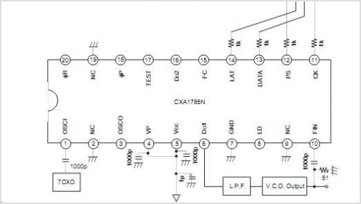
The CXA1821M is an integrated circuit designed for compact disc players. This IC includes an Automatic Power Control (APC) circuit along with RF, focus error, and tracking error amplifiers for 3-spot optical pickup output. It also supports voltage-converted optical...
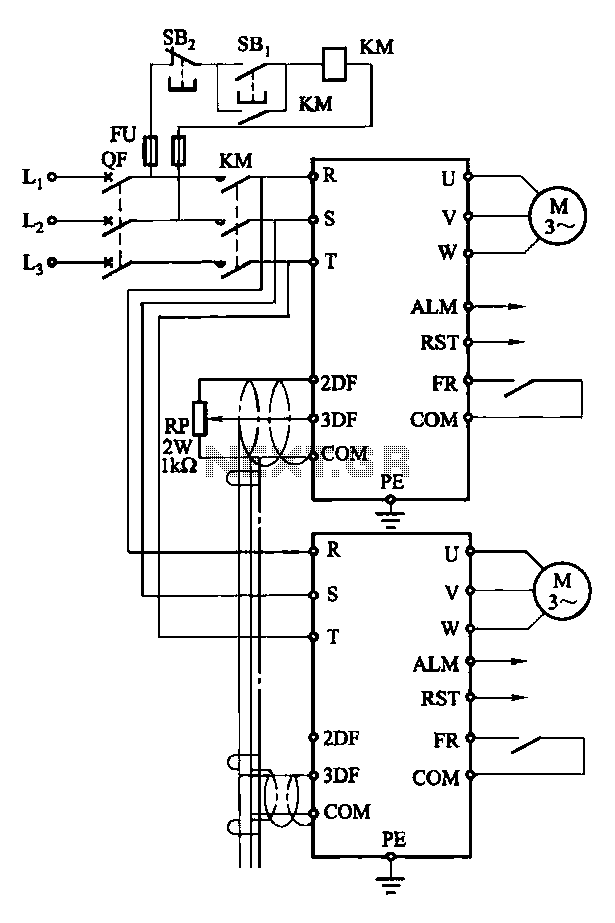
Each motor operates with an independent drive; however, only one frequency is utilized for a specific device. This setup employs a single RP potentiometer to control multiple motors in parallel. In this configuration, the circuit design allows for multiple motors to...
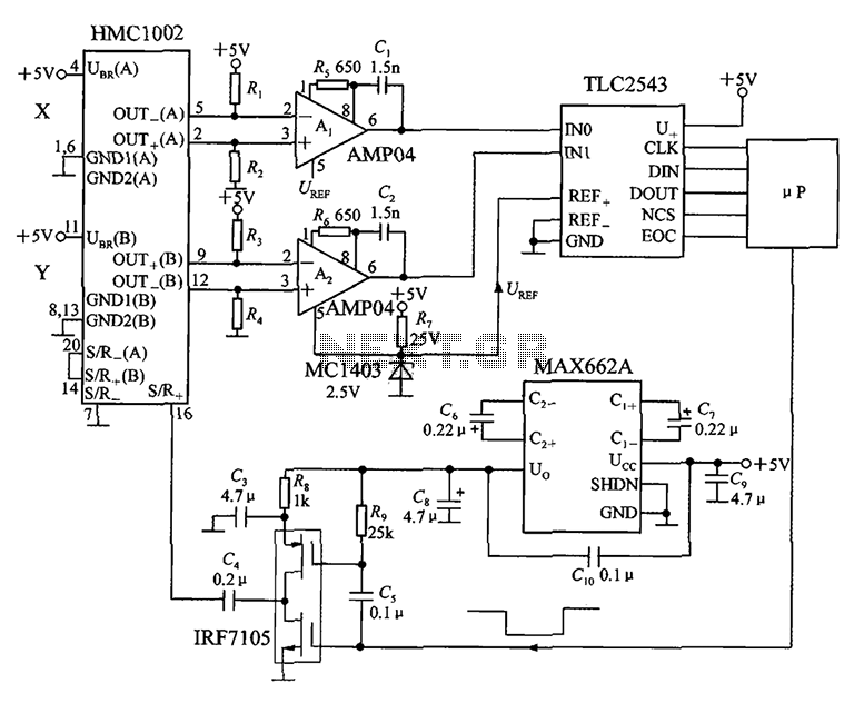
An application circuit for a biaxial magnetic field sensor is presented. This circuit utilizes the HMC1002 biaxial magnetic sensor along with two AMP04 amplifiers (A1, A2) to simultaneously measure magnetic fields in both the X-axis and Y-axis directions. The...
This document presents a very low-power monolithic 1.9GHz silicon Low Noise Amplifier (LNA) that operates with a total current consumption of 1.75mA, which includes the bias circuit. The described Low Noise Amplifier (LNA) operates at a frequency of 1.9GHz, making...
This design enables simultaneous handling of high-frequency signals and high toggle rates. Toggle rates of up to 1 MHz and megahertz signals are achievable with this circuit. The circuit is designed to manage high-frequency signals effectively while maintaining rapid toggle...
Multiple unit radio control: How to create a multi-unit radio control system. A multi-unit radio control system allows for the simultaneous operation of multiple devices or units using a single remote control transmitter. This system is commonly used in various...