
water alarm schematic
The LM1830 fluid detector IC is a specialized component intended for fluid detection applications. It operates at higher voltage levels, making it less suitable for battery-powered devices. Its design is focused on accuracy and reliability in fluid detection, but this comes at a higher cost and power consumption.
In contrast, the 74HC14 CMOS IC provides a more versatile and power-efficient alternative. Its lower operating voltage and minimal current draw make it particularly advantageous for battery-operated devices. The architecture of the 74HC14 includes six inverters, each able to function with hysteresis, which helps stabilize the input signal against noise and fluctuations.
The circuit design incorporates a feedback mechanism through resistor R1 and the water sensor, creating a reliable square wave signal generator. This configuration not only enhances the performance of the inverter but also ensures that the system remains stable and responsive. Resistor R2 plays a critical role in maintaining the input signal level, preventing oscillations that could lead to unnecessary power consumption.
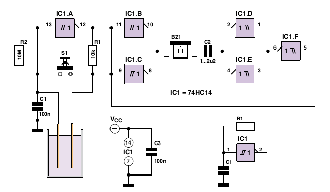
The piezo buzzer is driven by the remaining inverters, providing an audible alarm signal when fluid presence is detected. Capacitor C2 is strategically placed to block DC current during monitoring, thus preserving battery life and ensuring efficient operation. This design exemplifies a balance between functionality and power efficiency, making it suitable for various fluid detection applications, particularly in portable or battery-powered devices.The LM1830 fluid detector IC from National Semiconduc tor is designed to be able to detect the presence of fluids using a probe. This chip requires a relatively high supply voltage and is not the most frugal power consumer. It is also quite specialised so unless you are buying in bulk the one-off price is not cheap. An alternative circuit show n h er e uses a standard CMOS IC type 74HC14. It has the advantage of operating with a 3 V supply and consumes less than 1 µA when the alarm is not sounding, this makes it ideal for use with batteries. The 74HC14 has six inverters with hysteresis on their input switching thresholds. A capacitor (C1) and a feedback resistor (R1) is all that`s necessary to make an inverter into a square wave signal generator.
In the water alarm circuit the feedback resistor consists of R1 and the water sensor in series. R1 prevents any possibility of short-circuit between the inverter`s input and out-put. Resistor R2 defines the inverter`s input signal level when the sensor is not in water. Any open-circuit (floating) input can cause the inverter to oscillate and draw more current. The remaining inverters in the package (IC1. B to IC1. F) drive the piezo buzzer to produce an alarm signal. Capacitor C2 ensures that no DC current flows when the circuit is in monitoring mode (with the alarm silent) this helps reduce the supply current. 🔗 External reference
Related Circuits
This schematic diagram illustrates a water level sensor, detector, and monitor circuit. An alarm is also integrated into this circuit. It is designed to detect any fluid with a resistance below 900K ohms. The water level sensor circuit typically employs conductive...
This timer is intended for individuals seeking to achieve a tan while minimizing excessive exposure to sunlight. A rotary switch adjusts the timer based on six categorized photo-types. A photoresistor modifies the preset time value in relation to sunlight...
When the water level is below the steel rods, there is no contact between the metal can and the rods, which are supported by a small insulated wooden board. The circuit built around IC1 draws no current, resulting in...
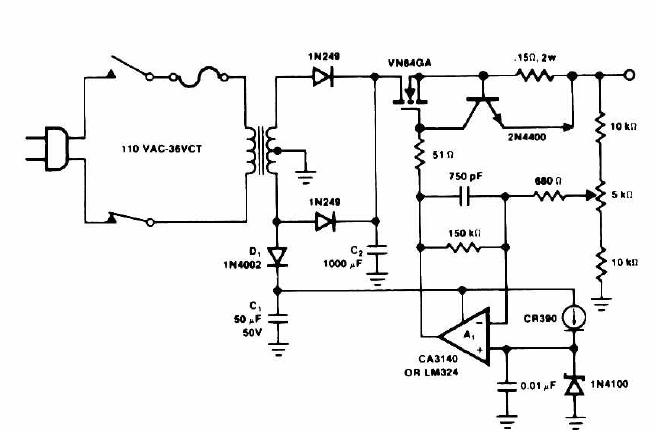
This circuit outputs a voltage of 14 volts with a maximum current of 4A. It can be used for NiCad batteries and accumulators, both wet and dry types. However, the accumulator must be rated for 12 volts and have...
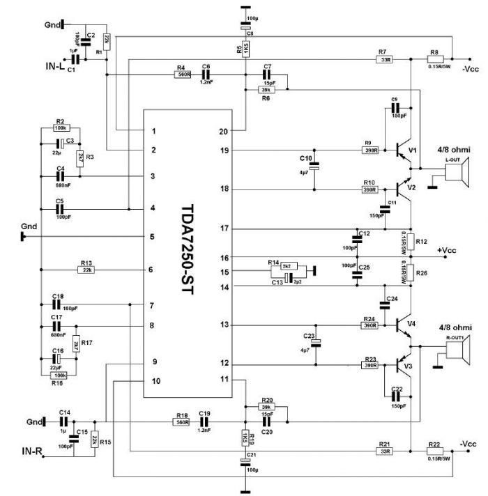
The TDA7250 audio driver, manufactured by SGS Thomson, can be utilized to design a straightforward high-power audio amplifier project with minimal external components. This audio amplifier can operate with either a 4-ohm or an 8-ohm load, delivering a maximum...
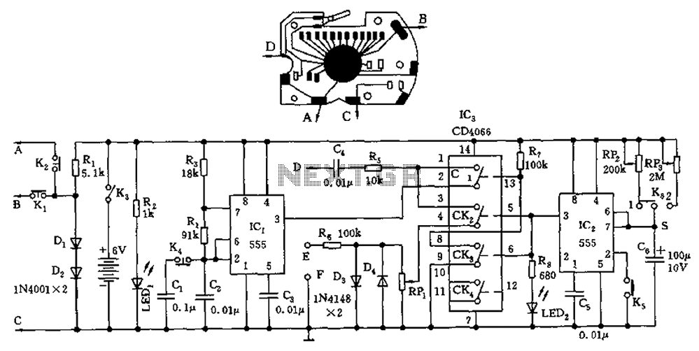
A circuit utilizing a standard digital quartz electronic watch, with its crystal soldered, forms a digital frequency meter as illustrated by the connected circuit. The test signal is applied to the E and F sides via components such as...