
555 Pocket digital frequency meter schematic

The described circuit operates as a digital frequency meter by leveraging the components of a standard digital quartz watch. The initial configuration involves soldering the quartz crystal, which is essential for the oscillator's function. The test signal is applied to designated points (E and F) through resistors and diodes that limit the signal strength, ensuring accurate measurements without overloading the circuit. The variable resistor RP1 allows for fine-tuning of the input signal, which is crucial for obtaining reliable frequency readings.
Upon activating the measurement process by pressing switch K5, the monostable delay circuit (IC2) is triggered, which sets the timing for the measurement. The analog switches (CK1, CK2, CK3) play a vital role in controlling the flow of the signal through the circuit, with CK2 and CK3 allowing the signal to pass while isolating the core memory circuit. This configuration ensures that the signal is processed correctly for frequency counting.
The integration of R5 and C4 serves to shape the signal for the counting circuit, establishing the necessary conditions for accurate frequency measurement. The counting circuit operates based on the input signal until the preset time elapses, at which point the state of the circuit changes to store the measured frequency in memory. This is indicated by the low signal from pin 3 of IC2, which disables the counting function and enables the storage of the frequency data.
To retrieve and display the measured frequency, the user presses K4, which activates the LCD to show the results. The circuit is designed to provide readings at two different scales: one file corresponds to a frequency multiplied by 1000 Hz, while two files correspond to a frequency of 100 Hz, allowing for versatile applications.
The timing switch K6 facilitates two distinct measurement periods, enhancing the circuit's functionality for various testing scenarios. The adjustments made via RP2 and RP3 during calibration ensure the accuracy of the timing intervals, which are critical for precise frequency measurement.
Overall, this circuit exemplifies an innovative use of digital watch components to create a practical and efficient frequency meter, showcasing the versatility and adaptability of electronic components in measurement applications. Circuit using an ordinary digital quartz electronic watch, the lower its crystal welding, as shown by the connected circuit constitutes a digital frequency meter. The test sign al is applied to E, F side by R6, D3, D4, etc. limiter, and adjust RP1, control the intensity of the input signal. When measuring, click K5, the IC2 monostable delay circuit is set, four analog switch IC3 (CD4066) of CK2, CK3 closed, CK1 off, form the core of memory circuit is cut off, the signal being measured by CK2, R5, C4 is added to form the core of the D point, form the core division, counting circuit starts operating. To be a preset time, IC2 of 3 feet referred to the low level, CK2, CK3 off, CK1 is closed, the signal to be measured into the memory state.
When reading, just click K4, the liquid crystal display panel will show the frequency of the signal to be measured. The timing switch K6 is divided into two tranches of 33 seconds and 328 seconds. When debugging, adjust RP3 at the second speed, timing of 328 seconds; adjust RP2 at the first speed for 33 seconds.
A positive figure point of access electronic watch, B point of access form the core of the upper end of the function keys, C point of access form the core negative reed, D point of access to any foot pads quartz crystal. The reading on the LCD screen when a file, the value is multiplied by the frequency 1000Hz, the value is multiplied by 2 files 100Hz.
Related Circuits

The circuit illustrated in Figure 1 generates a precise variable-frequency sine wave intended for use as a general-purpose reference signal. It incorporates an 8th-order elliptic switched-capacitor low-pass filter (IC3), which is clocked by a 100 kHz square wave produced...
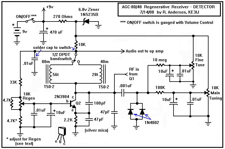
Here is a dual-band regenerative receiver that originated from encouraging communications with Jerry (K9UT) and another individual named Harvey, who constructed the original AGC-80 and its experimental successor, the AGC-80/30. Jerry has expressed his satisfaction with both receivers, noting...
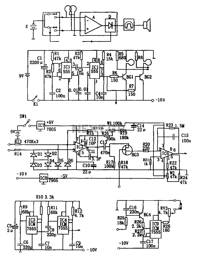
The figure illustrates a double coil metal detector circuit, which consists of a probe, a transmitter, a receiver, a timer, sound transmitters, and other components. The transmitter circuit, depicted in (b), is composed of a multivibrator (IC1, R1, R2,...
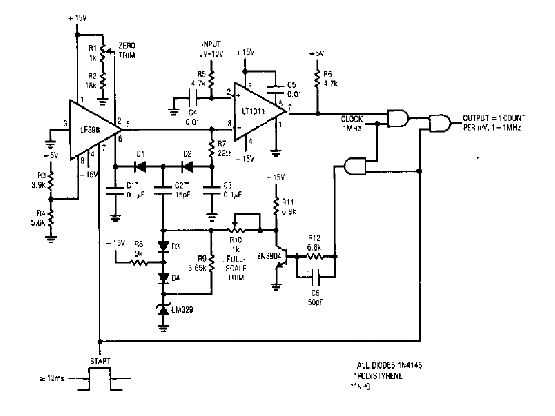
The simple 4-digit converter circuit has an output count of 1, designed to operate within a frequency range of f-IMHz to 10.000. All diodes used in the circuit are IN4146, and the capacitors are made of `POLYSTYRENE` NPO. The...
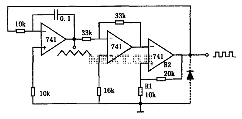
The circuit illustrated generates a variety of low-frequency waveforms, specifically triangle and square waves, simultaneously. It consists of several stages: the first stage is an integrator, followed by a gain stage with an inverter, and a comparator stage that...
Analog-to-digital converters (ADCs), printed-circuit board (PCB), microcontroller or digital signal processor (DSP), total-harmonic-distortion (THD), signal-to-noise ratio (SNR). Analog-to-digital converters (ADCs) are essential components in modern electronic systems, enabling the conversion of analog signals into digital form for processing by microcontrollers...