
Water Level Sensor/Detector/Monitor With Alarm
The water level sensor circuit typically employs conductive probes or electrodes that are placed at various levels within a tank or reservoir. When the water level rises to a certain point, the conductivity between the probes changes, triggering the sensor. The circuit can employ a comparator or a microcontroller to monitor the resistance values of the fluid.
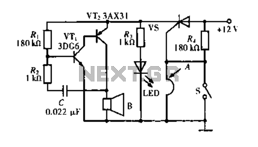
In this specific design, the alarm system is activated when the resistance of the fluid drops below the specified threshold of 900K ohms. This could indicate the presence of water or another conductive liquid, signaling the need for attention. The alarm can be a simple buzzer or a more complex sound system, depending on the application requirements.
Power supply for the circuit is typically provided through a DC source, ensuring that the sensor and alarm components operate reliably. Additional components such as resistors, capacitors, and possibly a relay may be included to condition the signal and control the alarm output effectively.
The schematic may also include safety features, such as diodes to prevent back EMF from damaging sensitive components, and filtering capacitors to stabilize the power supply and reduce noise. Overall, this circuit serves as a practical solution for monitoring water levels in various applications, including industrial tanks, aquariums, or home water systems.This schematic diagram shows a water level sensor/detector/monitor circuit. An alarm is also featured in this circuit. Any fluid with a resistance under 900K.. 🔗 External reference
Related Circuits
This low voltage circuit can be used to monitor batteries and other volatile sources of current for problems. The circuit sounds an alarm and lights an LED, but can be interfaced to any number of other circuits for many...
The MAXQ3210 is a powerful RISC microcontroller. This device has features and capabilities that make it suitable for battery-powered applications that require detection. The MAXQ3210 microcontroller is designed with a focus on low power consumption and efficiency, making it particularly...
The locker alarm circuit, also known as the cashbox watcher, is designed to safeguard a cashbox or locker from unauthorized access. This reliable design features a foolproof, remotely operated alarm and electromagnetic relay driver that receives its control signal...
This is a quiz bell/alarm circuit designed to indicate the fastest finger first. The circuit includes one bulb for the quiz master and one for each contestant. The bulbs illuminate when a button is pressed. The cathode of the...
The circuit operates based on a principle where the SCR (Silicon Controlled Rectifier) trigger is grounded, keeping it in the off state. When a burglar triggers the alarm, a voltage is supplied to the SCR trigger, turning it on....
This section includes intruder alarms for homes, cars, and motorcycles, as well as power failure alarms, water level alarms, and a snore detector. All circuits are organized alphabetically on the Circuit Index page and chronologically on the update page....
Warning: include(partials/cookie-banner.php): Failed to open stream: Permission denied in /var/www/html/nextgr/view-circuit.php on line 713
Warning: include(): Failed opening 'partials/cookie-banner.php' for inclusion (include_path='.:/usr/share/php') in /var/www/html/nextgr/view-circuit.php on line 713