
Water AlarmCircuit
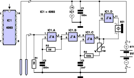
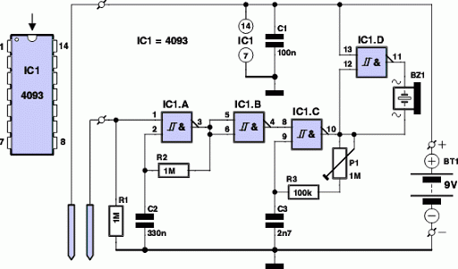
The electronic water alarm circuit employs a 4093 IC, which is a quad 2-input NAND gate with Schmitt-trigger inputs, ensuring reliable operation in the presence of noise and fluctuations in the signal. The circuit uses two probes that serve as electrodes, which are strategically placed at the lowest point where water may accumulate. When water bridges the gap between the probes, it completes the circuit, allowing current to flow through the conductive water and triggering the oscillator circuit formed by the combination of IC1a, R2, and C2.
The oscillator generates a square wave signal that drives the buzzer, producing an audible alert. The frequency of the oscillation can be adjusted by modifying the values of R2 and C2, allowing for customization of the alarm's sound to suit user preferences. The pitch can also be fine-tuned using a potentiometer (P1), enhancing the effectiveness of the alert by ensuring it is loud and attention-grabbing.
IC1d functions as a power amplifier, increasing the voltage supplied to the buzzer, which results in a more pronounced audio signal. This is crucial for ensuring that the alarm is heard in various environments. The use of insulated and twisted wires for the probe connections minimizes the risk of false alarms due to electromagnetic interference from nearby electronic devices.
The low current consumption of the circuit when idle ensures that the battery life is extended, making this water alarm a practical solution for early leak detection in residential and commercial settings. Regular maintenance and monitoring of the battery are recommended to prevent leakage and ensure continued operation of the alarm system.Have you ever seen the stairs to one of the upper stories in your house turn into a waterfall Or maybe you`ve come home to find your aquarium fish trying to swim across the carpet For your sake, we hope not, because the consequences are usually fairly dramatic. With a handful of electronic components, you can at least ensure that you will be war ned before you have to put on your waders. It`s better to prevent water problems than to have to correct them. But no how many precautions you take, an occasional leak can still happen. A burst water supply hose for the washing machine, a bath tap that someone forgot to turn off, a broken aquarium wall, or a leaking boiler or central heating tank anything is possible. In such cases, it`s nice to be warned as quickly as possible, for example by an acoustic water alarm.
Then you can at least limit the damage. If you`re handy with a soldering iron and know the difference between an IC and a PC, you`ll no doubt enjoy building the electronic water alarm described here. The circuit takes advantage of the fact that normal` water is always slightly contaminated, even if only slightly, and thus conducts electricity to a certain extent.
It is built around an popular IC from the somewhat antiquated 4000-series logic family: the 4093. This IC contains four inverted-output AND gates (NAND gates) with Schmitt-trigger inputs. If water is detected between the probes, it emits an intermittent and rather irritating beeping tone. The conductivity of the water is used to active the circuit built around IC1a. The two electrodes (probes) are fitted at the lowest point where water will come to stand. They can be two tinned copper wires, but you can also use two pieces of circuit board with the copper surface coated with solder.
The combination of IC1a, resistor R2 and capacitor C2 forms a simple oscillator that produces the intermittent (on/off) effect of the alarm. If no water is present between the probes, the input of IC1a is held low by R1 and the output of IC1b is also low.
The oscillator is not active in this state. If moisture is sensed, the supply voltage pulls input 1 of gate IC1a high via the conductive water, causing the gate to start oscillating. Whenever the output of IC1b is high, the tone generator built around IC1c is enabled, and in turn it energizes buzzer BZ1.
The net result is a periodic, intermittent beeping tone. You can adjust the intermittent effect of the sound produced by the water alarm to suit your taste by simply adjusting the value of R2 or C2. You can also set the pitch of the sound with P1. The closer the pitch is to the resonant frequency of buzzer BZ1, the louder the tone will be. You should set the sound to the most irritating level possible. Gate IC1d is used to boost the amount of power than can be pumped into the buzzer. It inverts the output signal from IC1c to double the voltage applied to the buzzer. Naturally, the circuit of the alarm must be fitted somewhere that will remain high and dry. Use a pair of thin twisted wires to connect the electrodes (probes) to the board. Naturally, you should use insulated, flexible wire for this purpose. Twisting the wires together makes the relatively long connection between the probes and the circuit less sensitive to false alarms due to external electromagnetic interference.
The current consumption is very low (less than 0. 1 µA) when everything is dry. When the buzzer is energized, the current consumption can rise to around 2mA. We measured 3mA with the frequency set to the maximum value. The battery will thus last for several years as long as no water is detected. Of course, you should bear in mind that the battery might start leaking after a while 🔗 External reference
Related Circuits

A flashing LED signals the necessity to water a plant. Very low current consumption - 3V powered circuit. This circuit is intended to signal when a plant is needing water. A LED flashes at a low rate when the...
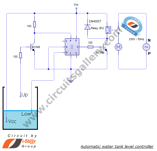
The automatic water level controller circuit is a straightforward engineering project that can automatically switch a domestic water pump on and off based on the water level in a tank. This motor driver circuit can be implemented at home...
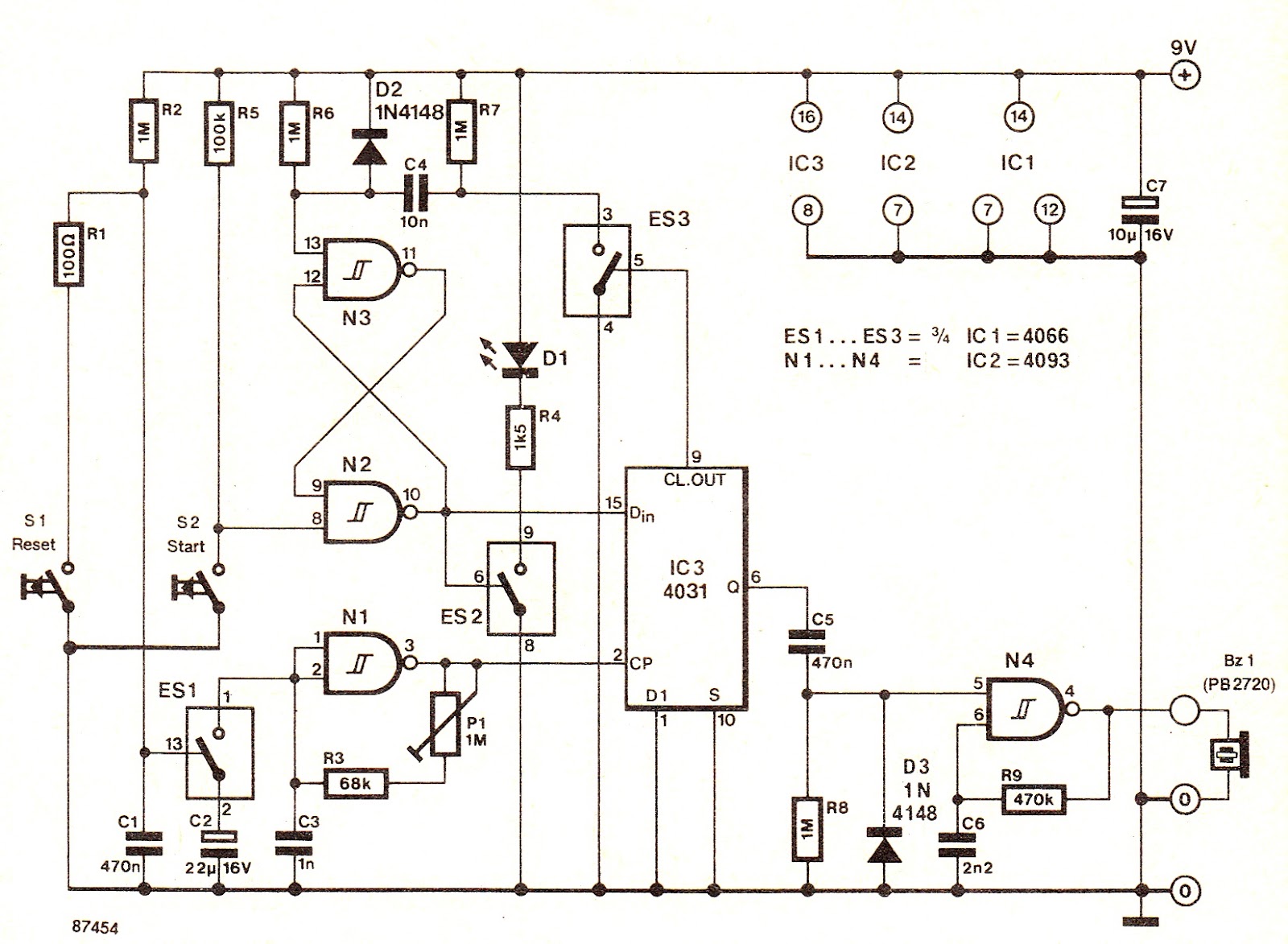
The electronic switch ES1 connects the frequency-determining capacitor to the input of clock oscillator N1. The logic level present at the Dm terminal of the integrated circuit is shifted to output Q at a speed defined by P1, allowing...
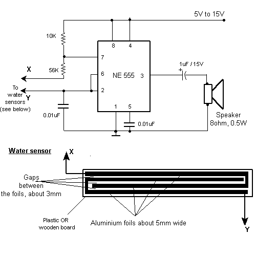
This circuit activates an alarm when its sensor comes into contact with water. It employs a 555 astable multivibrator that generates a tone of approximately 1 kHz upon water detection. The circuit consists of a 555 timer configured in astable...
Have you ever seen the stairs to one of the upper stories in your house turn into a waterfall? Or maybe you've come home to find your aquarium fish trying to... The provided description suggests a scenario involving unexpected water...
The loop can be any type of hookup wire, with a maximum resistance of about 90K. Using very thin wire (40AWG, for example) will create a highly sensitive trip wire, but will reduce the distance it can be strung...