
Bathroom Water Heater Timer
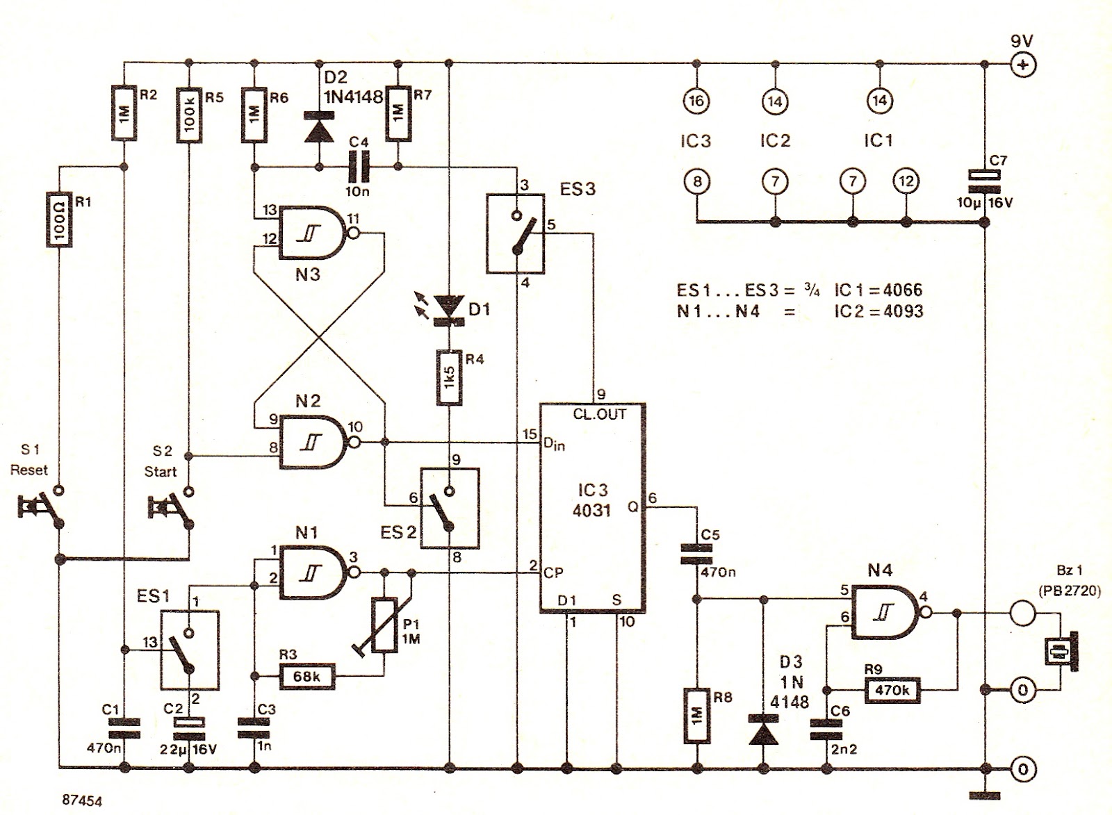
The electronic circuit described functions as a timer specifically designed for photographic processing, particularly during the fixing stage. The core component of the system is the electronic switch ES1, which plays a crucial role in connecting the frequency-determining capacitor to the clock oscillator N1. This connection is vital for generating the timing intervals necessary for the fixing process.
The timing mechanism is controlled by a variable resistor P1, which adjusts the speed at which the logic level transitions from the Dm terminal of the integrated circuit to the output Q. This feature allows for precise timing adjustments, accommodating a range of fixing times, typically set to 9 minutes for standard photographic processes.
Activation of the timer occurs through the pressing of the START button, which triggers the S-R bistable flip-flop. The illumination of LED Dt indicates that the timer is operational. A positive pulse at terminal CP writes a logic high into the shift register, which consists of 64 stages. As the clock pulses are applied, the shift register accumulates the logic high state, ultimately enabling oscillator N4 to drive the piezoelectric buzzer Bz1 after completing the designated count.
The system incorporates a reset mechanism that automatically deactivates the LED shortly after the START button is pressed, due to the reset pulse generated by the CL.OUT output of IC1. This design ensures that the user is not distracted by the LED indicator once the timing process has commenced.
Powered by a 9V battery, the circuit is optimized for low power consumption, not exceeding 10 mA. This efficiency is essential for prolonged use during photographic development sessions. The timer's capability to "remember" up to 32 different immersion times enhances its functionality, allowing it to provide auditory signals when each specific timing interval has elapsed, thus assisting users in managing the fixing process effectively.
Overall, the design integrates multiple electronic components to create a reliable and user-friendly timer for photographic fixing, significantly improving the accuracy and convenience of the process.Electronic switch ES1 connects the frequency determining capacitor to the input of clock oscillator N1. The logic level that exists at the Dm terminal of IC; is shifted towards output Q at a speed that is defined by P1, which enables defining fixing times between roughly 1 and l0 minutes, 9 minutes being a commonly used value.
When the star ·r but ton is pressed, S ”R (set-reset) bistable toggles, and LED Dt lights. A logic l is written into the shift register with the aid of a positive pulse transition applied to terminal CP. After 64 clock pulses from the logic high level is available at the out- ` put of the shift register, and p enables oscillator N4 to drive i piezoelectric buzzer Bzi.
The LED is turned off shortly after the START button is pressed, because the bistable is reset by the CL. OUT pulse from ICL The timer is conveniently fed from a 9 V battery, and should not consume more than about 10 mA.
When, after developing, photo- graphs are immersed in the fixing bath at irregular intervals, it becomes difficult to observe the correct fixing time for each of these. When the fixing interval has lapsed, the timer provides a short beep. The circuit is composed of a 64-stage shift register which is l loaded with zeroes on power up, because it lacks a reset input.
This problem is solved by the present timer, which is capable of "remembering" up to 32 immersion times, and automatically provides a signal when a photograph is to be taken out of the bath. 🔗 External reference
Related Circuits
The clock timer utilizes a PIC16F628 microcontroller to display time in a 3.5-digit format and manage an external load. It features a calendar that accounts for leap years and optional daylight saving time adjustments. The timer output can be...
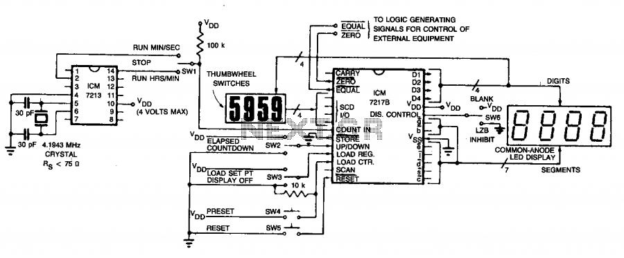
The circuit employs an ICM7213 precision timebase generator with a frequency of 4.1943 MHz, which is utilized for generating pulses that are counted by an ICM7217B counter. Thumbwheel switches are incorporated to allow the user to input a starting...
This schematic represents a simple water or liquid level sensor relay switch circuit, designed to control electronic appliances based on water levels. The circuit is particularly useful for automatically turning off a water pump when a water tank, pool,...
The circuit diagram represents a water-activated relay circuit. This circuit employs two transistors configured as a high-gain compound pair. The transistors used are 2N2222A for T1 and T2, which may also be substituted with BC108. The current gain is...
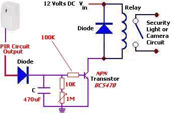
The following circuit illustrates a PIR Sensor Timer Circuit Diagram. Features include a simple design, enhanced accuracy, and efficiency. Components involved are a diode, among others. The PIR (Passive Infrared) Sensor Timer Circuit is designed to detect motion through infrared...
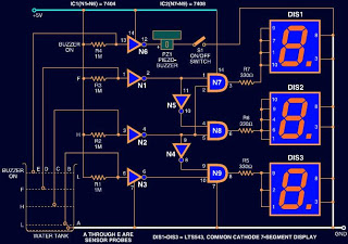
Circuits designed to indicate water levels typically consist of LEDs to represent the liquid level. However, this circuit utilizes a 7-segment LED display instead of standard LEDs for a numeric representation of the water level. Additionally, a buzzer is...
Warning: include(partials/cookie-banner.php): Failed to open stream: Permission denied in /var/www/html/nextgr/view-circuit.php on line 713
Warning: include(): Failed opening 'partials/cookie-banner.php' for inclusion (include_path='.:/usr/share/php') in /var/www/html/nextgr/view-circuit.php on line 713