
water level alarm circuit
The water level alarm circuit typically consists of a few key components: two conductive probes, a comparator or operational amplifier, a resistor, a piezo buzzer, and a power supply. The probes are positioned at specific heights to detect the water level. When water bridges the gap between the probes, it completes the circuit, allowing current to flow.
The operational amplifier is configured as a comparator. It compares the voltage across the probes with a reference voltage set by a resistor divider network. If the voltage from the probes exceeds the reference voltage, the output of the comparator switches state, activating the piezo buzzer. This buzzer generates an audible alarm, alerting users to the water level condition.
The circuit is powered by a suitable DC power supply, which can range from 5V to 12V, depending on the components used. Proper placement of the probes is crucial; they should not be too close to prevent false triggering due to minor fluctuations in water levels. Additionally, the probes must be made of a corrosion-resistant material to ensure longevity, especially in environments with varying water quality.
This water level alarm circuit can be effectively used in various applications, including monitoring water levels in tanks, aquariums, and swimming pools, providing a practical solution for water level management.Here is the schematic of a water level alarm circuit. The circuit will work as a water level sensor and will give a melodious alarm sound when the two probes in the circuit will detect water. You can use this water level indicator circuit to detect the level of water in any place for example in swimming pool, For using the circuit simply attach th
e two probes on the desired level of water on which you want the indication and make two to three inches gap between the two probes. 🔗 External reference
Related Circuits
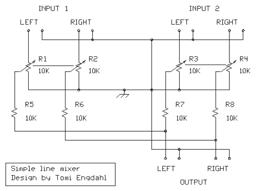
The mixer circuit described features three line inputs and three microphone inputs. The microphone inputs are designed for low impedance dynamic microphones with a range of 200 to 1000 ohms. Alternatively, an electret condenser microphone (ECM) can be used,...
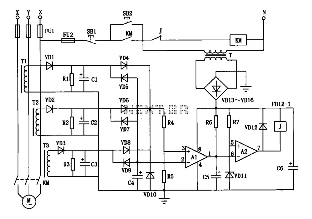
A current three-phase motor phase protection circuit is designed to detect three-phase current using homemade small current transformers T1, T2, and T3. The current signals are collected by rectifiers VD1, VD2, and VD3, while capacitors C1, C2, and C3...
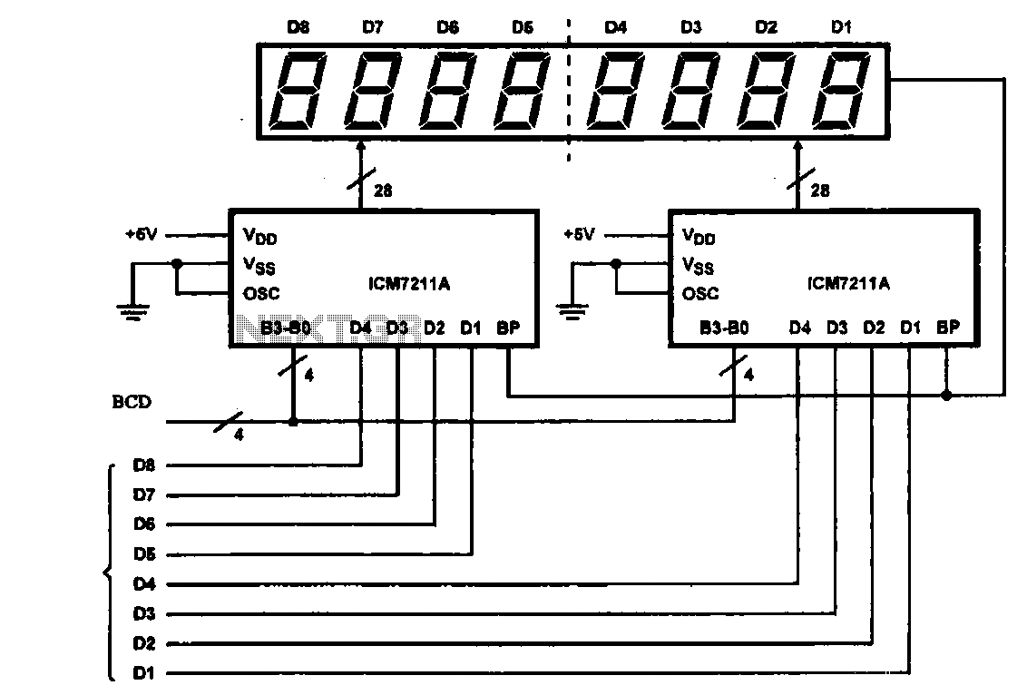
This circuit illustrates an 8-digit digital tube display driver, utilizing two ICM7211A integrated circuits. A BCD (Binary-Coded Decimal) to binary data signal is transmitted to the BO-B3 pins of the ICM7211A. The digital signals are divided into two groups...
Light-emitting diodes (LEDs) can be powered using direct current (DC), alternating current (AC), and pulse drivers. A typical buck LED display circuit is illustrated in Figure 13-1. The current-limiting resistor (R) for LED tubes can be calculated using the...

The automatic alarm circuit comprises a DTMF automatic dialing system, a password control circuit, a voice detection and alarm circuit, a telephone interface circuit, a power supply circuit, and a keyboard display circuit. The automatic dial-up alarm utilizes the...

This servo system is designed to track the sun. Sunshine is focused onto a 50mm round image using an optical lens, and a 3DU33 photosensitive transistor is positioned at the light slit of AA' and BB'. It is essential...
Warning: include(partials/cookie-banner.php): Failed to open stream: Permission denied in /var/www/html/nextgr/view-circuit.php on line 713
Warning: include(): Failed opening 'partials/cookie-banner.php' for inclusion (include_path='.:/usr/share/php') in /var/www/html/nextgr/view-circuit.php on line 713