
Water-level indicator

Press switch SI to reset the circuit.
The circuit operates by monitoring the liquid level through two probes that detect conductivity. When the liquid reaches a certain level, it bridges the gap between the probes, allowing current to flow. This current triggers the SCR, which is a type of semiconductor device that can control power. Once the SCR is activated, it allows current to flow through the warning device (WD1), which then emits an audible or visual alert to notify users of the high liquid level.
The choice of the warning device can vary based on application requirements; a Sonalert provides an audible signal, while a lamp or buzzer can serve as visual or auditory alerts, respectively. The inclusion of diode D1 is critical for protecting the circuit from voltage spikes that may occur when the SCR switches off. This transient suppression helps to enhance the reliability and longevity of the circuit components.
To reset the system after an alert, the user must press switch SI. This action interrupts the circuit, allowing the SCR to turn off and the warning device to deactivate, thereby resetting the system to its initial state. The design ensures that the circuit remains operational and responsive to changes in liquid levels, providing essential monitoring capabilities in various applications, such as sump pumps, tanks, or other liquid storage systems.In this a warning device WD1 is in series with SCR1. When the liquid level causes a conductive path between the probes, the SCR conducts sounding WD1. The warning device may be a Sonalert (TM), a lamp or a buzzer.D1 acts as a transient suppressor. Press SI to reset the circuit.
Related Circuits
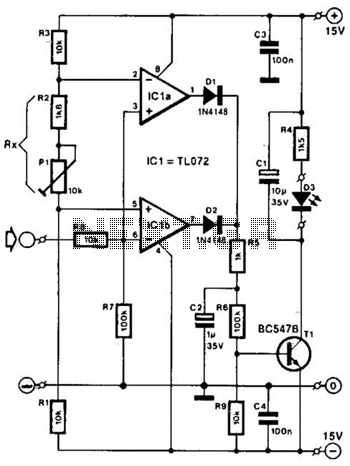
Two operational amplifiers are utilized as comparators to signal an excessive magnitude of an audio frequency (AF) signal, regardless of whether the signal is positive, negative, or asymmetrical. A reference voltage is established for both operational amplifiers using a...
This LED (Light Emitting Diode) display consists of 10 LEDs to indicate the level of an input signal. If the signal is low, only LED #1 will light up. As the signal level increases, the illuminated dot will progress...
This simple and slightly odd circuit can clearly show the level of the supply voltage (in a larger device): as long as the indicator has good 12 volts at its input, LED1 gives steady, uninterrupted (for the naked eye)...
The circuit activates a light corresponding to the first button pressed in a "Who's First" game. While three stages are illustrated, the circuit can be expanded to accommodate any number of buttons and lights. The circuit design employs a series...
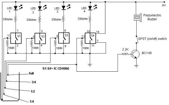
A low-cost water level indicator circuit can be designed using this schematic. This water level indicator utilizes a CMOS IC, the CD4066, to indicate the amount of water present in an overhead tank and provides an alarm when the...
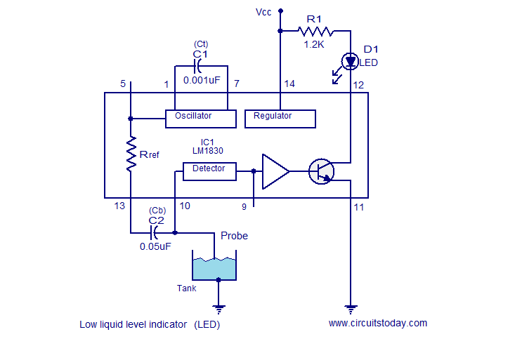
The following circuit illustrates a Liquid Level Sensor Indicator Circuit utilizing the LM1830 integrated circuit. Features: Manufactured by National Semiconductors, the device... The Liquid Level Sensor Indicator Circuit employing the LM1830 IC is designed to detect and indicate the level...