
game show indicator lights whos first

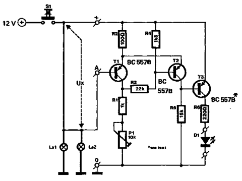
The circuit design employs a series of push-button switches, each representing a participant in the game. When a button is pressed, it sends a signal to a logic circuit that determines which button was activated first. This logic circuit can be composed of a combination of flip-flops or a priority encoder, which is capable of identifying the first button pressed among multiple inputs.
In the basic configuration, three buttons are connected in parallel to the logic circuit. Each button is connected to a pull-down resistor to ensure that the input remains low when not pressed. When a button is pressed, it pulls the corresponding input high, triggering the logic circuit to output a signal.
The output of the logic circuit is then connected to a light-emitting diode (LED) or a lamp, which illuminates to indicate the first button pressed. The circuit can be designed to include a debounce mechanism to prevent false triggering due to mechanical bounce when the button is pressed.
For scalability, additional buttons and lights can be incorporated by cascading more logic circuits or by utilizing multiplexers. This allows the circuit to handle a larger number of participants without significant redesign. The power supply for the circuit should be appropriately rated to support the total current draw from all connected lights.
In summary, this circuit design offers a flexible and expandable solution for a "Who's First" game, providing a clear visual indication of the first participant to press their button. Proper consideration of debounce and power management will enhance the reliability and performance of the circuit.The circuit turns on a light corresponding to the first of several buttons pressed in a ""Who`s First"" game. Three stages are shown but the circuit can be extended to include any number of buttons and lamps.. 🔗 External reference
Related Circuits

This circuit utilizes battery-powered blinking warning lights for roadblocks. It can operate on AC power to create barricades with warning indicators. The circuit incorporates an NE555 timer and resistors RP1 and RP2, along with resistor R1, to form a...

This jam circuit can be used in quiz contests wherein any participant who presses his button (switch) before the other contestants, gets the first chance to answer a question. The circuit given here permits up to eight contestants with...

The SH-805 circuit serves as a holiday lights controller, as illustrated in Figure 2-64. It is similar to the SH-804 circuit board, although the pin locations and control functions differ. By pressing the SB button, users can select between...

This circuit utilizes a dual operational amplifier to drive a rectifier and emitter-follower configuration, which indicates AC current on an LED. The inductor L1 is formed by a winding of a audio transformer, created with a pick-up coil consisting...
The circuit described below monitors the car's brake lights and indicates their operational status using a 12V light-emitting diode (LED). This functionality can prevent fines for driving with defective brake lights and enhance road safety. The monitor relies on...
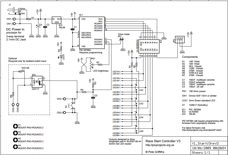
The circuit described on this page is designed around Kingbright's 52mm LED cluster module which comprises 50 red LEDs in a waterproof housing with a brightness in excess of 16000mcd. In the original version of this project each LED...