
LED Audio Level (VU) Indicator and Alarm: The Dot Turns to Bar When The Signal Reach The Maximum Le
 Indicator and Alarm: The Dot Turns to Bar When The Signal Reach The Maximum Le")
The LED display circuit described utilizes the LM3914 integrated circuit to visually represent the amplitude of an audio signal through a series of ten LEDs. The architecture of the circuit is designed to provide a clear indication of signal levels, making it suitable for audio applications where level monitoring is essential. The LM3914 operates in a linear mode, where each LED corresponds to a specific voltage level within the specified range of 0-1.2V. The circuit's design allows for a straightforward interpretation of audio levels, with the first LED lighting up at minimal signal levels and subsequent LEDs illuminating as the signal strength increases.
To enhance the performance of this circuit, particularly when dealing with audio signals that fluctuate rapidly, a peak detector is integrated into the design. This component captures the peak voltage of the audio signal, ensuring that the LEDs display a stable indication of the signal level rather than a rapidly changing flicker. The use of a single transistor peak detector is recommended, as it provides sufficient resolution to differentiate between adjacent LEDs, which is critical for accurate audio level representation.
For applications requiring a logarithmic representation of audio levels, the LM3915 is a suitable alternative to the LM3914. This chip is pin-compatible, allowing for easy substitution. However, it is important to note that the logarithmic display necessitates a more precise peak detection mechanism to maintain accuracy at lower signal levels. Implementing a precision half-wave peak detector will enhance the circuit's ability to reflect subtle changes in audio amplitude, resulting in a more nuanced and responsive visual indication.
Overall, this LED display circuit serves as an effective tool for monitoring audio levels, providing clear visual feedback that is crucial for audio engineering and performance applications. The choice of components and the design approach ensure that the display remains responsive and accurate across the intended range of audio signals.This LED (Light Emitiing Diode) display consist of 10 LEDs to indicate the level of an input signal. If the signal is small, only LED#1 will light, and if the signal level getting higher then you`ll se the light dot will move through LED #2, #3, #4, and so on. When the signal input drive the dot until LED #9 lights, the next increasing input s ignal won`t only move the dot to LED #10, but it turn on all the LEDs, changing the dot to a full-scale bar. This give you a better alarm to show you that the maximum level has been reached. The input signal is detected by the chip at pin 5, and it should range between 0-1. 2V. This range is suitable for standard audio line (line-out) level. This circuit uses LM3914 which has linear scaling for the LED, the indication move linearly with the input signal: if the input is maximum then the LED#10 will light (and all other LED`s because the alarm fuction is working), if the input is at half maximum then the LED#5 or #6 will light, LED #1 will light when the signal is 1/10 of the maximum.
To show well defined dot position representing audio level (VU, voltage unit) as we percept, we need to feed this circuit using the output of a peak detector. Connecting directly to audio signal would give fast blinking display with vague dot position, since audio signal is actually oscillate between an equilibrium point.
The single transistor peak detector is suitable for this purpose, because the resolution of two adjacent LEDs is slightly more than 100mV. Logarithmic display give more representative indication when dealing with audio signal, since we naturally percept the sound level in logarithmic manner, a change from 9 to 10 is not really noticed as the change from 1 to 2 in sound wave amplitude.
We percept the first one as being almost no change while the last one is twice louder, although both cases show the same one absolute unit change. For the logarithmic scale, National Semiconductor provide other series, with pin-to-pin compatible with LM3914, and it`s LM3915.
Just change the chip with LM3915 and the display will be in logarithmic scale. But wait, you need more precise peak detector for logarithmic scale, since the display will have more precise resolution at low level indication. The precision half-wave peak detector would be suitable for this circuit. Using logarithmic scale indicator, you`ll notice good dynamic indication in almost all level of your volume control.
[Circuit schematic diagram source: National Semiconductor Application Notes] 🔗 External reference
Related Circuits
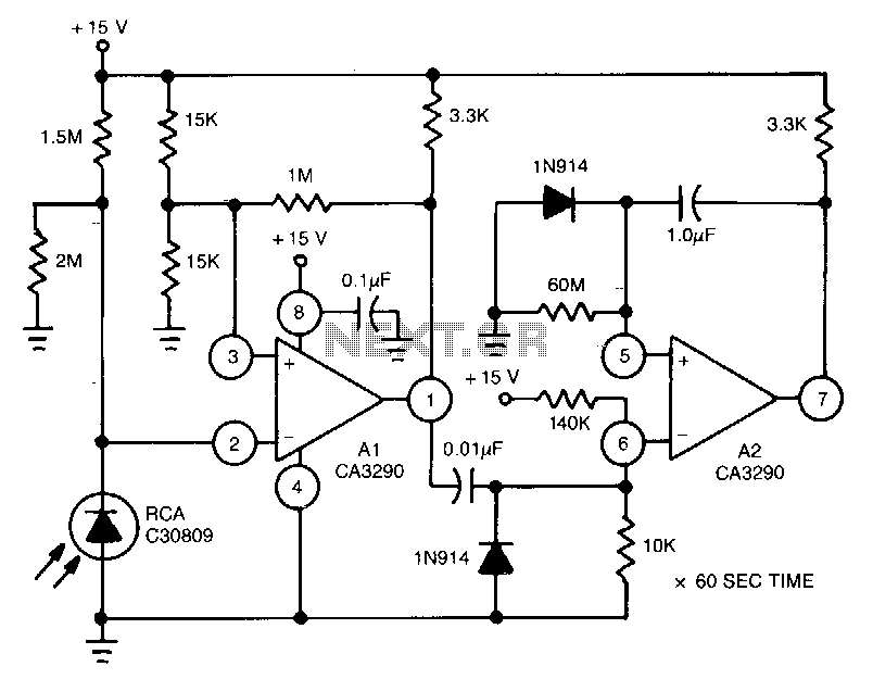
This circuit utilizes the CA3290 BiMOS dual voltage comparator to detect variations in the current of a light-emitting diode (LED). The output from the comparator triggers A2, a one-shot timer. If the light source to the photodiode is disrupted,...
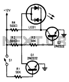
With switch SI open, base bias is supplied to transistor Q2 through a voltage divider formed by resistors R2 and R3, which activates the green element of the LED. This indicates that power is being supplied to the project....
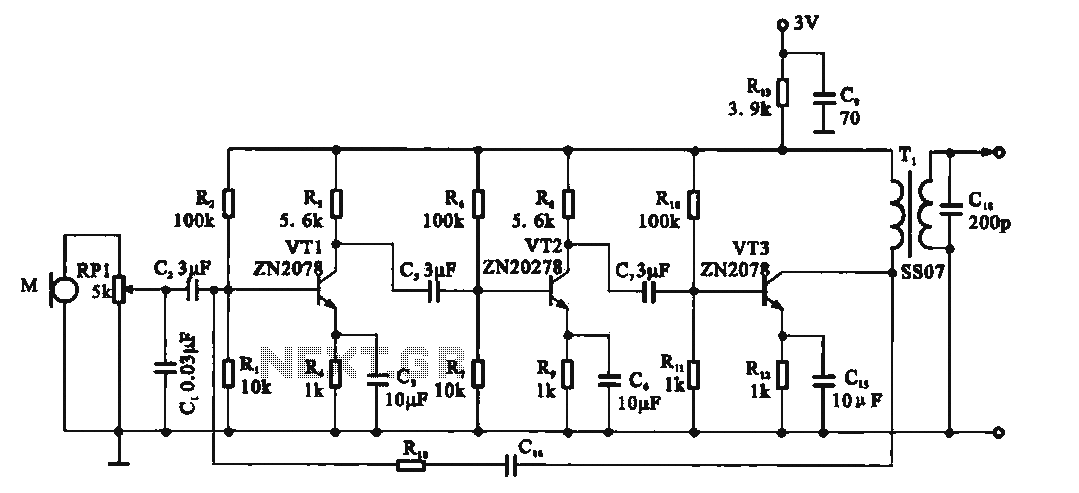
This circuit is a recording signal amplifying transistor circuit that illustrates the functioning of a microphone signal amplifier. After adjustment through potentiometer RP1, the signal is applied to the transistor VT1, which operates as a common emitter amplifier. The...
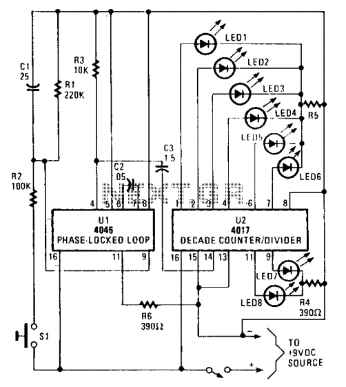
The circuit utilizes a 4046 Phase-Locked Loop (PLL) that incorporates a voltage-controlled oscillator (VCO), two phase comparators, a source follower, and a Zener diode to generate a low-frequency pulsed output of approximately 40 Hz. The frequency range of the...
This circuit diagram represents a radio-controlled system, commonly used in toy car applications for children. The circuit consists of two main parts: the transmitter and the receiver. The transmitter generates radio signals using an oscillator circuit formed by transistor...

Ideal for operating 3 to 24V DC existing on-circuit lamps. This circuit was designed to provide continuous light for lamps already wired into a circuit. The circuit is intended to facilitate the operation of existing DC lamps that are integrated...