
Water-level sensing and control
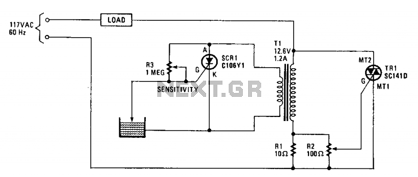
The described circuit utilizes a transformer-based control mechanism to manage water levels through a triac and SCR (Silicon Controlled Rectifier). The primary side of transformer T1 is connected in series with resistor R1, establishing a relationship between the load and the primary impedance. The configuration is designed to detect changes in water levels via a probe that interacts with SCR1.
When the water level is low, the probe remains above the water surface, causing SCR1 to activate. This activation draws current, creating a significant load on the transformer's secondary winding. The load's impedance is reflected back to the primary side, which influences the gate voltage of triac TR1. If the load is an electric valve or similar device, it will remain operational until the water level rises sufficiently to contact the probe.
Upon contact with water, the probe shorts the gate and cathode of SCR1, resulting in the SCR turning off. This action effectively removes the load from the secondary winding of the transformer, transitioning the system into an open-circuit state. The resulting change in impedance at the primary side eliminates the gate trigger signal for triac TR1, leading to the deactivation of the water supply.
The circuit is versatile, allowing for various applications such as controlling irrigation systems via a relay or managing solenoid valves in decorative water features like garden ponds. The design ensures reliable operation and responsiveness to water level changes, making it suitable for automated water management systems.The operation of the circuit is based on the difference in the primary impedance of a transformer when its secondary is loaded and when it is open-circuit. The impedance of the primary of Tl and resistor Rl are in series with the load. The triac's gate-control voltage is developed across parallel resistors Rl and R2. When the water level is low, the probe is out of the water and SCR1 is triggered on. It conducts and imposes.a heavy load on transformer Tl's secondary winding. That load is reflected back into the primary, gating triac TR1 on, which energizes the load. If the load is an electric value in the water-supply line, it will open and remain open until the water rises and touches the probe, which shorts SCRl's gate and cathode, thereby turning off the SCRl, which effectively open-circuits the secondary. The open-circuit condition—when reflected back to the primary winding—removes the triac's trigger signal, thereby turning the water off.
The load may range from a water valve, a relay controlling a pump supplying water for irrigation, or a solenoid valve controlling the water level in a garden lily pond. 🔗 External reference
Related Circuits
A one-button control switch is designed to control two relays, each of which can switch the load power on and off as needed. The circuit primarily consists of a hex inverter CD4049 and two self-locking DC relays. The circuit utilizes...

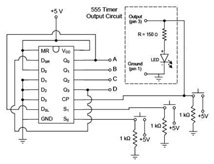
An infrared (IR) remote control circuit for managing home appliances can be constructed using a Decade Counter CD4017, a 555 Timer, and a TSOP1738 infrared receiver. This circuit allows users to control home devices with a standard remote control,...
The circuit shows the method of mirror current sensing a MOSFET. A fully conducting MOSFET is resistive and behaves exactly as a resistor. It therefore you limit the voltage across the MOSFET when it is conducting you automatically limit...
A motor coil requires controllers to adjust its position and speed. A motor driver is necessary to amplify the low output current from a controller to a larger current required by the motor. The following article describes how to...
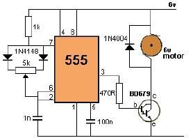
This project utilizes a 555 timer to control the speed of a 6-volt DC motor. Speed adjustment is achieved by rotating a 50 kΩ potentiometer either to the left or right. The circuit employs the 555 timer in astable mode,...

A, B, and C are used for a large power split-phase system. The A + BC range generator phase line features an A-A indole path string containing two 220V/15W bulbs. The bulbs recover based on macro instructions from J...