
Design a Unipolar Stepper Motor Controller/Driver and
The design of a unipolar stepper motor controller/driver involves several critical components and concepts. The unipolar stepper motor operates by energizing its coils in a specific sequence, allowing for precise control of position and speed. This motor type typically has five or six wires, with each coil having a center tap connected to a voltage source. The controller must ensure that the coils are energized in the correct order to achieve smooth stepping motion.
BJT transistors are often utilized in the driver circuit to switch the power to the motor coils. These transistors act as electronic switches that can handle the higher current required by the motor, thereby protecting the controller from damage due to excessive current draw. The choice of transistors must consider the motor's voltage and current ratings, ensuring that the transistors can operate within safe limits.
A universal shift register, such as the 74HC194, is commonly employed to control the sequence of signals sent to the motor driver. This shift register allows for easy manipulation of the control signals, enabling the user to set the stepping direction and speed. The pin-out of the shift register provides information on how to connect it to the rest of the circuit, including power supply and control lines.
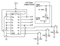
The schematic for the stepper motor driver circuit typically includes connections for the motor coils, the BJT transistors, and the universal shift register. Additional components, such as resistors and capacitors, may be included to ensure stable operation and to filter out noise. The inclusion of an LED circuit can serve as a visual indicator of the motor's operation, providing feedback on the stepping process.
To enhance the performance of the stepper motor, modifications to the output circuit may be necessary. These modifications can include adjusting the voltage connections to the motor and implementing an astable oscillator to generate clock pulses for the shift register. This oscillator can provide a variable frequency output, allowing for precise control over the motor's speed.
In summary, the design and implementation of a unipolar stepper motor controller/driver require a thorough understanding of motor operation, driver circuit components, and control signal sequencing. The integration of these elements results in a robust system capable of precise motor control for various applications.given motor coil while motor need controllers to adjust position and speed. Then you will needa motor driverto amplify a controller`s low output current to a larger current that is required by a motor. Below is an article that describe you about how to design a unipolar stepper motor controller/driver.
You will be taken into sections that will des cribe you onunipolar stepper motorand BJT transistors, learn how to use a universal shift register, and put it altogether to design unipolar stepper motor driver (using a Jameco 15 V unipolar stepper motor). Within the article, there are explanation about The advantages and disadvantages between unipolar, bipolar and DC motors, Ways of energizing stepper motor coils in the proper sequence, Variable Speed Stepper Motor Drive, and Microcontroller Stepper Motor Control.
Also, there areDiagram of Unipolar Stepper Motor, Schematic of Unipolar Stepper Motor, Universal Shift Register (74HC194) Pin-Out, Operation of Universal Shift Register, Schematic of Stepper Motor Driver Circuit with LED circuit added, Output Circuit Modification, Motor Voltage Connection, and Astable Oscillator Output Used as Clock-Pulse Generator circuit diagram. 🔗 External reference
Related Circuits
The 74AC240 stepper driver works by alternately enabling each half of the buffer. Only one half can be enabled at a time. Let’s assume that the top half of the driver is enabled. U1A & U1B along with R8,...
For optimal efficiency, set MAX_STEPPERS to the number of stepper motors being controlled, with a maximum limit of four. Motors are identified by indices 0, 1, 2, and 3. On the QCard, there is a trade-off between the number...
This article discusses practical techniques for incorporating "correctness by design" in DDR2 interfaces from a Signal Integrity (SI) perspective, utilizing the current generation of available design tools. It analyzes common DDR2 design errors and the trade-offs between various popular...
The motor vehicle currently represents a no-emission automotive solution, serving as a green means of transportation that is expected to significantly impact human society in the 21st century. The direct-flow brushless electric machine has emerged as a leading technology...

Designed for Birkbeck, the microscope controller is an open-source stepper motor driver that utilizes an Arduino Uno and an Arduino stepper motor shield to operate a Phytron ZSS32 200 1.2A 3V stepper motor. The sample port movement is facilitated...
The second half controls the steering. The mechanical design is a 3 wheeled caddy with the single wheel actually a closely spaced pair of wheels which are driven by the main drive motor to provide motive power (this is...