
DC motor control using 555 timer circuit
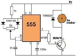
The circuit employs the 555 timer in astable mode, which generates a pulse-width modulation (PWM) signal to control the average voltage supplied to the DC motor. The frequency and duty cycle of the PWM signal are determined by the values of the resistors and the potentiometer connected to the timer.
In this setup, the 50 kΩ potentiometer is connected in series with a fixed resistor, creating a voltage divider that influences the timing characteristics of the 555 timer. As the potentiometer is adjusted, the resistance changes, altering the width of the pulses generated by the timer. This, in turn, changes the effective voltage applied to the DC motor, allowing for smooth speed control.
The DC motor is connected to the output of the 555 timer through a suitable transistor or MOSFET, which acts as a switch to handle the higher current required by the motor. A diode should be placed in parallel with the motor terminals to protect the circuit from back EMF generated when the motor is turned off.
Power supply for the circuit should be stable and capable of providing the necessary voltage and current for both the 555 timer and the DC motor. Proper decoupling capacitors are recommended to filter out any noise in the power supply lines.
This 555 timer motor control circuit is ideal for applications where variable speed is needed, such as in robotics, fans, or other motor-driven devices. The simplicity of the design, combined with the effectiveness of PWM control, makes it a popular choice among hobbyists and engineers alike.Using this 555 timer DC motor control electronic project you can control speed of a 6 volts DC motor, by simply rotate left or right the 50 k potentiometer. 🔗 External reference
Related Circuits
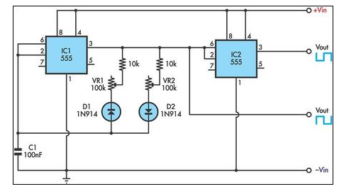
This circuit allows for the independent variation of the on/off times of a 555 timer across a wide range. This capability is not achievable with a conventional 555 timer circuit. The described circuit enhances the functionality of the standard 555...
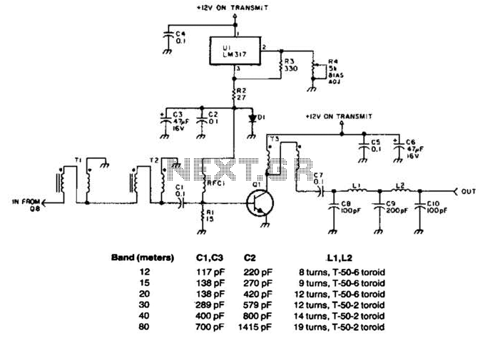
This linear amplifier provides a 10-W PEP output with a 1.25-W drive on the 10 m band. The transformers, T1, T2, and T3, consist of 10 turns of bifilar windings on an FT-50-43 toroidal core and are designed for...
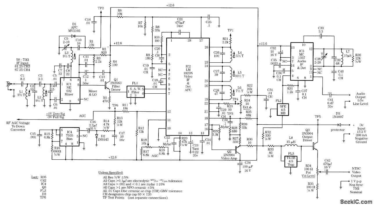
Radio-frequency schematics (also see NE602 datasheet and application note). This page contains electronic circuits related to RF receivers. This index features a broad collection of RF receiver circuits. Radio-frequency (RF) schematics are essential for designing and implementing circuits that operate...
The circuit comprises a 3-stage resistor-capacitor coupled amplifier. When ring button S2 is pressed, the amplifier circuit formed around transistors T1 and T2 gets converted into an asymmetrical astable multivibrator generating ring signals. These ring signals are amplified by...
Create a temperature-controlled fan circuit using a 15V AC power supply instead of a 230V AC supply. Clarification is needed on whether it is necessary to change the triac and resistor in the provided diagram. Additionally, it is important...
Men often appreciate the convenience of television remote controls, which can sometimes frustrate their female partners. They tend to switch channels frequently, wanting to ensure they do not miss anything while a specific program is on. With the remote...