
Fastest Quiz Bell/Alarm
The quiz bell/alarm circuit operates by utilizing a combination of bulbs and a button mechanism to indicate which contestant has pressed their button first. The circuit is designed with a 9V Zener diode that regulates the voltage to ensure stable operation. When a contestant presses their button, the associated bulb lights up, signaling their response. The quiz master’s bulb also illuminates, indicating that the quiz master is aware of the response.
The reset mechanism is critical for ensuring that only the first contestant's response is acknowledged. By employing a normally closed push button as the reset switch, the circuit is designed to disconnect the power supply while the button is pressed, effectively resetting the system for the next question. The use of cross-coupled SCRs allows for a robust first-response monitoring system, ensuring that once a contestant has pressed their button, the circuit prevents others from activating their bulbs until reset.
The interlocking circuit design enables a latching mechanism that can manage multiple push buttons. This feature is beneficial in quiz scenarios, as it allows for a clear indication of the first response while preventing confusion among contestants. The Zener regulator ensures that voltage levels remain within acceptable limits, enhancing the reliability of the circuit.
Furthermore, the audio amplifier stage of the circuit serves to amplify any audio signals that may be generated, providing clear sound output for the quiz master or audience. It operates efficiently with a low current draw of approximately 30 milliamps from a 9-volt supply, making it suitable for compact applications.
Safety precautions are emphasized, particularly regarding the transformerless power supply. Users are advised against touching the circuit while it is powered to prevent electric shock, as it lacks isolation from the mains supply. Overall, this quiz bell/alarm circuit exemplifies an efficient and effective design for interactive quiz applications, incorporating essential electronic components to deliver reliable performance and safety.This is aquiz bell/alarm circuit. This circuit indicate fastest finger first . This circuit has one bulb for Quiz master and one for each contestant. The bulb will illuminate when a button is pressed. the cathode of the 9v1 zener sees approx mid-rail voltage. The Quiz Master bulb is also illuminated. Here is the circuit: There is no other bulbs can be lit until the circuit is reset because The zener comes out of conduction and no voltage appears across the 120R resistor. The reset switch must be a normally closed push button, to disconnect the power supply when it`s being pressed.
A pair of cross-coupled SCRs can be used to build a first-response monitor circuit, as shown in the schematic diagram below. First-response circuit is popular in quiz application where the first contestant who press the button will prevent the other Continue reading †’.
This is a switching circuit that provide latching mechanism to make a set of radio buttons using push buttons. This circuit consist of interlocking circuit that manipulate the signal to latch and release the previous latched section.
The circuit latches Continue reading †’. The figure below show us a zener regulator. The essential component is the dropping resistor R which the value given by (V-Vo)/I, where I is the desired output plus 10%. As long as the supply voltage V is constant, the Continue reading †’. This is a little audio amplifier, it is similar to the audio amplifier which is used in small transistor radio.
This circuit draws about 30 milliamps from a 9 volt supply. This circuit consist of two stage. First stage is Continue reading †’. WARNING: Don`t touch any part of the circuit when the circuit is running (connected to the powerline), this circuit is not isolated from mains supply. This is transformerless power supply circuit. This circuit is used to generate fixed voltage power Continue reading †’. 🔗 External reference
Related Circuits
This design utilizes four integrated circuits (ICs) and features four input circuits with four independent outputs, along with a single master reset switch. The outputs are configured with light-emitting diodes (LEDs), which can be modified to control lamps or...

There have been several requests for a quiz circuit, leading to the development of a design featuring four inputs that can be easily modified. This circuit employs four integrated circuits (ICs) and includes four input circuits with independent outputs,...
A pair of cross-coupled SCRs can be utilized to create a first-response monitor circuit, as illustrated in the schematic diagram below. The first-response circuit is... In the context of electronic monitoring systems, a first-response monitor circuit employing cross-coupled Silicon Controlled...
This project is designed for a quiz competition involving up to four contestants or teams. Each contestant is equipped with a trigger push-switch and an LED. When a trigger switch is activated, it illuminates the corresponding LED, activates a...
There have been several requests for a quiz circuit, leading to the development of a four-input design that can be easily modified. This design utilizes four integrated circuits (ICs) and features four input circuits, four independent outputs, and a...
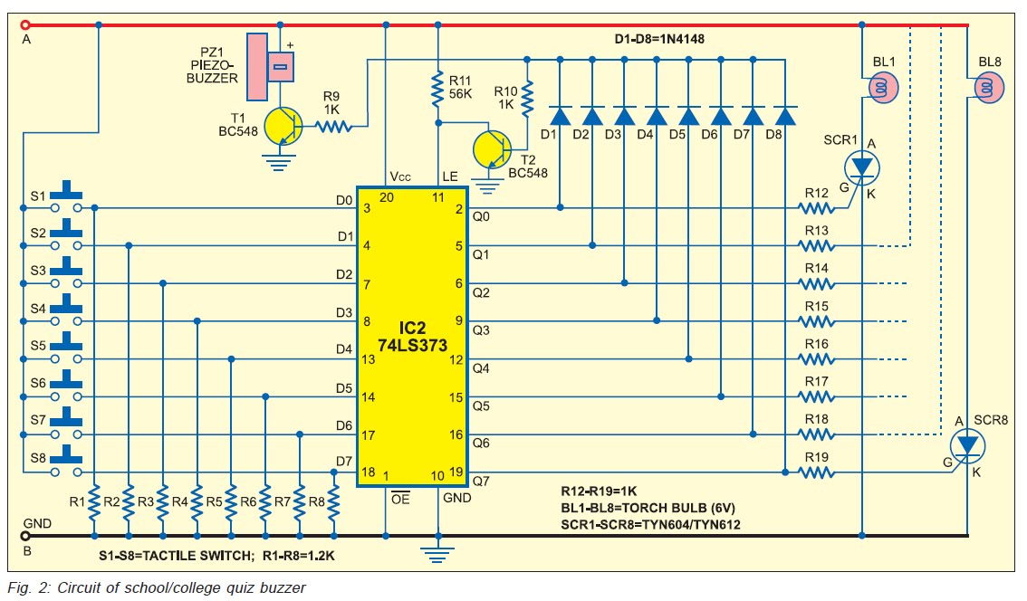
Manual buzzers used for quiz competitions in schools and colleges often create confusion in identifying the first respondent. While there are circuits that utilize PCs and discrete ICs, these options can be either too expensive or limited to a...
Warning: include(partials/cookie-banner.php): Failed to open stream: Permission denied in /var/www/html/nextgr/view-circuit.php on line 713
Warning: include(): Failed opening 'partials/cookie-banner.php' for inclusion (include_path='.:/usr/share/php') in /var/www/html/nextgr/view-circuit.php on line 713