
Wein Bridge Oscillator using ic 741 op amp
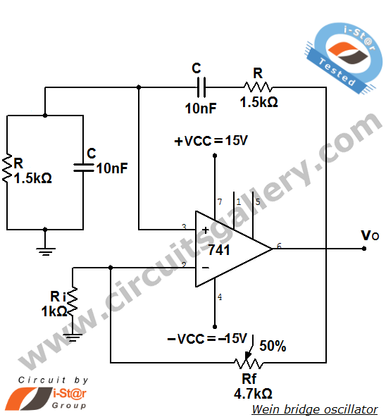
The Wien bridge oscillator circuit is characterized by its unique configuration that enables it to produce a stable sine wave output. The operational amplifier (741) is pivotal in this design, as it amplifies the signal while maintaining the necessary phase relationships for oscillation. The circuit typically incorporates a combination of resistors and capacitors to form the necessary RC networks. The series RC network is designed to introduce a specific time constant that, in conjunction with the parallel RC network, defines the frequency of oscillation.
In the Wien bridge oscillator, the resistors Ri and Rf serve as part of the feedback loop, which is crucial for determining the gain of the amplifier. The feedback factor β of 1/3 indicates that for every unit of output, one-third is fed back into the inverting input of the op-amp. This feedback mechanism is essential for achieving the condition of sustained oscillation, where the loop gain must equal one.
The selection of resistors and capacitors in the circuit directly influences the frequency of the generated sine wave. By adjusting the values of these components, the oscillation frequency can be fine-tuned for specific applications, making the Wien bridge oscillator versatile in various electronic applications. Additionally, the circuit's design allows for easy implementation and modification, contributing to its popularity in audio frequency generation tasks.
Overall, the Wien bridge oscillator is an effective solution for generating stable sine waves, with its operational amplifier configuration providing both simplicity and reliability in electronic design.Wien bridge oscillator is an audio frequency sine wave oscillator of high stability and simplicity. Before that let us see what is oscillator An oscillator is a circuit that produces periodic electric signals such as sine wave or square wave. The application of oscillator includes sine wave generator, local oscillator for synchronous receivers et
c. Here we are discussing wein bridge oscillator using 741 op amp IC. It is a low frequency oscillator. The op-amp used in this oscillator circuit is working as non-inverting amplifier mode. Here the feedback network need not provide any phase shift. The circuit can be viewed as a wien bridge with a series RC network in one arm and parallel RC network in the adjoining arm. Resistors Ri and Rf are connected in the remaining two arms. At resonant frequency ( ’o), the inverting and non-inverting input voltages will be equal and in-phase so that the negative feedback signal will be cancelled out by the positive feedback causing the circuit to oscillate.
From the analysis of the circuit, it can be seen that the feedback factor ²= 1/3 at the frequency of oscillation. Therefore for sustained oscillation, the amplifier must have a gain of 3 so that the loop gain becomes unity.
🔗 External reference
Related Circuits
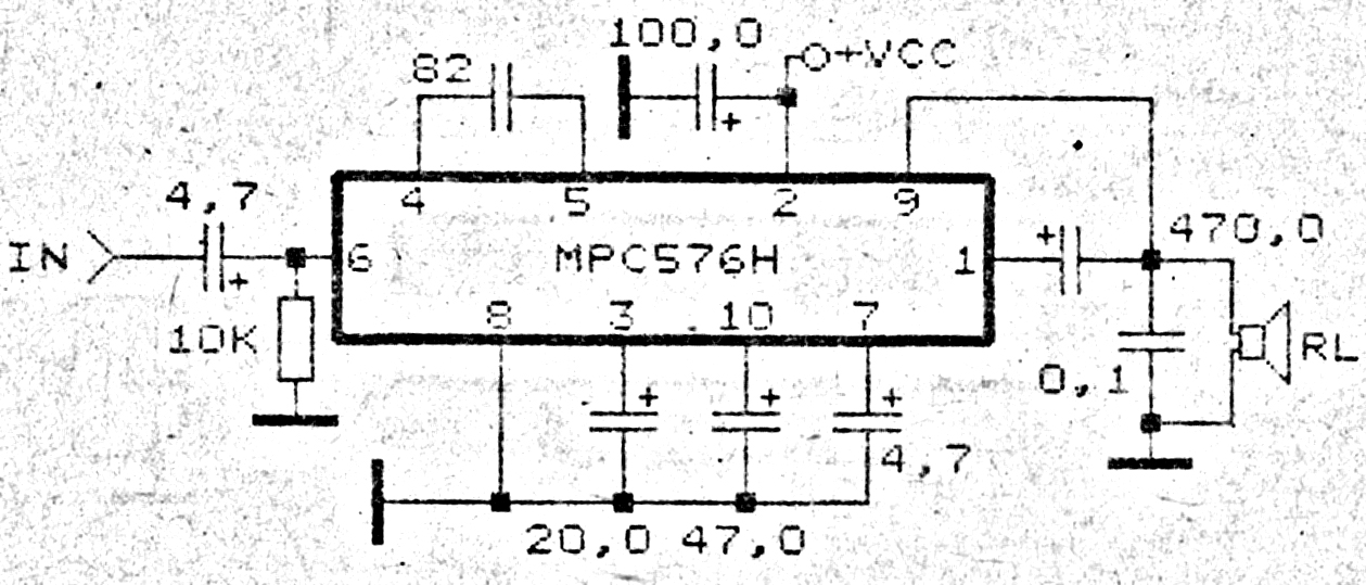
This amplifier circuit exhibits good sound quality. Although it does not provide high output power, it is capable of producing both soft and loud sounds reliably. The circuit utilizes a single IC, the MPC576H, along with several supporting components....
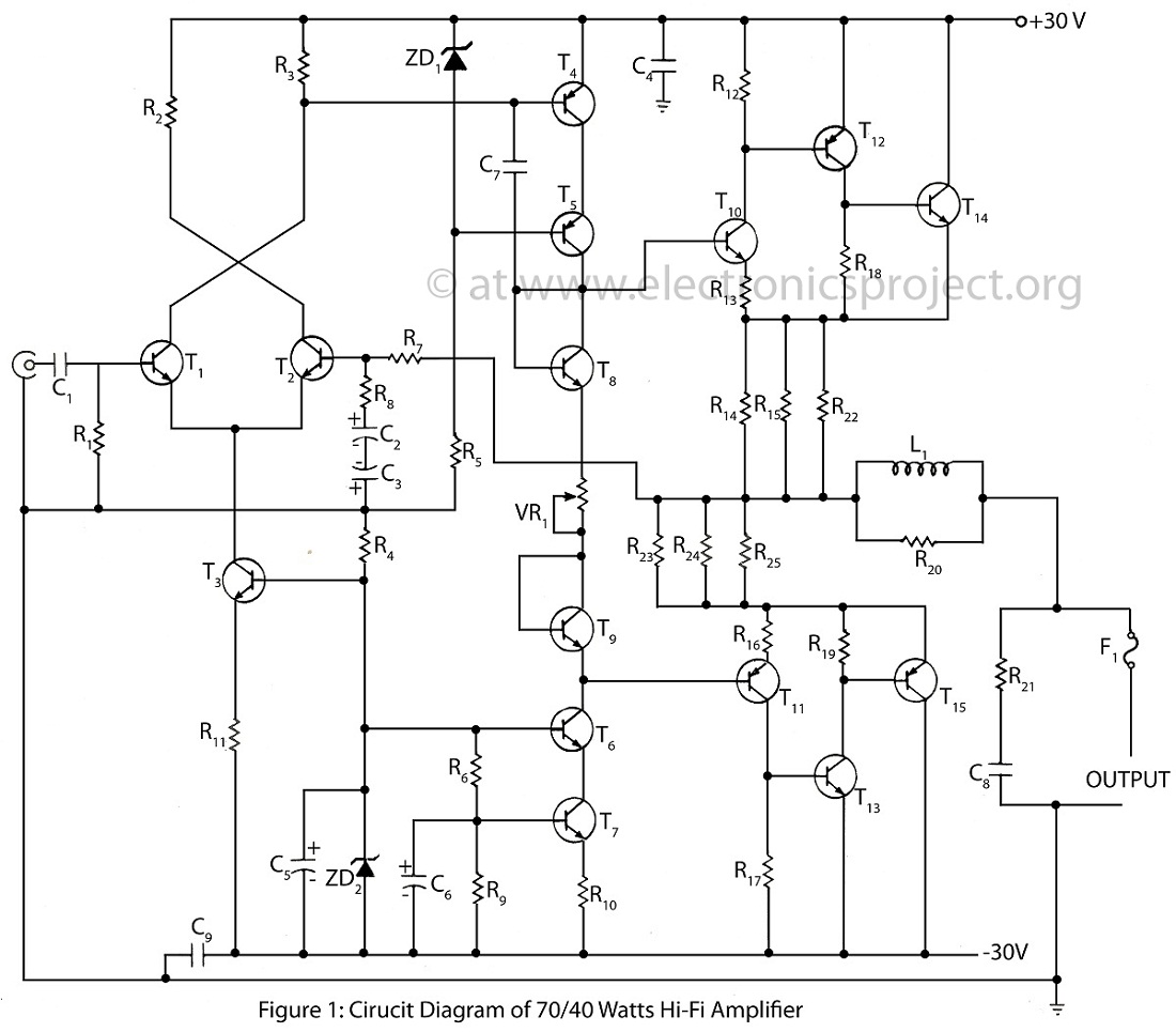
The 70/40 Watts Hi-Fi amplifier is an advanced and high-quality audio amplifier that features an almost 0% distortion circuit design. This amplifier is renowned for its exceptional sound quality and performance. The 70/40 Watts Hi-Fi amplifier utilizes a sophisticated circuit...
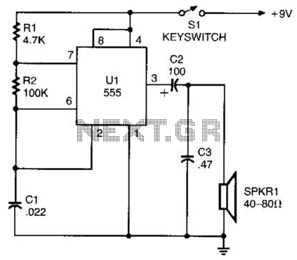
A 555 timer configured as an astable multivibrator is used in this circuit to generate an audio note. The capacitance value can be changed to vary the audio note as desired. The circuit utilizes a 555 timer IC, which...
The circuit utilizes standard components, produces a good sine wave, and exhibits a degree of immunity to the specific operational amplifier it is designed around. However, it can be easily misunderstood, and oversimplifications regarding its operation may lead designers...
The Oscillator Design Guide is integrated into Agilent EEsof's Advanced Design System environment, functioning as a smart library and interactive handbook for creating effective designs. It enables quick oscillator design, interactive characterization of components, and provides in-depth insights into...

This module utilizes the highly integrated MAX2830 RF transceiver, providing a complete RF front-end solution that complies with the WLAN IEEE 802.11b/g standard. The MAX2830 RF transceiver is designed for wireless communication applications, specifically targeting WLAN systems. It integrates various...