
Analysis of a Digitally Controlled Wien Bridge Oscillator
The Wien Bridge oscillator is a classic electronic circuit used to generate sine waves. It operates based on the principle of positive and negative feedback, which is critical in achieving sustained oscillations. The circuit typically includes an operational amplifier, resistors, and capacitors arranged in a specific configuration to create a feedback loop. The resistors R1 and R2, along with capacitors C1 and C2, form the Wien Network, which is responsible for determining the frequency of oscillation. The frequency of oscillation can be calculated using the formula:
\[ f = \frac{1}{2\pi R C} \]
where \( R \) represents the resistance and \( C \) represents the capacitance in the Wien Network. The gain of the op-amp must be carefully set to ensure that it compensates for the attenuation introduced by the feedback network, thus allowing for stable oscillation.
The design of the Wien Bridge oscillator can be sensitive to component tolerances, particularly the capacitors, which can significantly affect the output frequency and waveform quality. This is why selecting high-quality capacitors with low tolerance is essential for precise applications. Additionally, the circuit may incorporate a light bulb or thermistor in some designs to provide automatic gain control, allowing the oscillator to maintain stable oscillation amplitude.
In summary, the Wien Bridge oscillator is a versatile circuit that can produce high-quality sine waves for various applications, including audio signal generation and waveform shaping. Understanding its operation and the relationships between its components is crucial for effective design and implementation.It uses standard components, gives a good sine wave and is fairly immune to the type of op ampit is designed around. It can, however, be misunderstood, and over simplifications as to its operation can leave the designer thinking that it is not as well trained as originally thought.
In pursuit of gaining an understanding of our trusty friend, it is wise to go back to basics. The circuit of a standard Wien Bridge oscillator is shown in Figure 1. A circuit will oscillate if, at a given frequency, it has greater than unity gain and zero phase shift from input, through the device, through the feedback network and back to the input. Looking at the circuit in Figure 1, R1 and C1 produce a positive phase shifted current with respect to the output voltage.
When this current meets R2 and C2, these components produce a voltage that is phase shifted in a negative direction. At one frequency the phase shift caused by R1 and C1 will be offset by an equal and opposite phase shift caused by R2 and C2 and the net phase shift will be zero.
The circuit is now in danger of oscillating. For the mathematically inclined, the transfer function of the network made up by R1, C1, R2, C2 can be considered. Since the output impedance of the op amp will be low and the input impedance of the inputs very high, it is relatively straightforward to derive the transfer function of the Wien Network (the resistive divider made up of R1 and C1 on the top and R2 and C2 on the bottom).
One strong cup of coffee and a rainy Sunday afternoon yields the transfer function as: Put simply (if this is possible) the imaginary `j` terms represent a 90 ° phase shift in the transfer function (either positive or negative). The real, non `j` terms represent zero phase shift in the transfer function. As the magnitude-of the real and imaginary terms change, so does the resultant phase shift. It can be seen from Equation 1 that at: the real terms in the denominator equate to zero, leaving only imaginary terms in the numerator and denominator.
Dividing the numerator and denominator by `jw` leaves no imaginary terms and hence no phase shift. We therefore have our condition for zero phase shift at a given frequency. Now, to greatly simplify things, it is wise to equate R1 to R2 and C1 to C2. It can then be seen that at resonance the transfer function from output to input is: To meet the requirements for oscillation (zero phase shift and unity gain), the op amp circuit needs to have a gain of three to overcome the attenuation resulting from the Wien Bridge network. Looking at this another way, to keep the two inputs of the op amp at the same voltage, the resistor network from the output to the inverting input needs to provide an attenuation of three to match the attenuation of the Wien Network.
This is very convenient in theory, but near useless in practice. We can obtain resistors with accurate values but obtaining accurate capacitors is a bit more difficult. Getting capacitors with an accuracy greater than 20% starts to eat into the design budget, so it is now wise to consider the effect of different capacitor values on the performance of the circuit.
Figure 2 shows a simple spreadsheet illustrating the values of the Wien Bridge Network and their impact on the gain. Cell B7 is the transfer function represented in Equation 3, cell B12 is represented by Equation 2 (with the answer in kHz) and cell B9 is the reciprocal of cell B7.
If C1 = C2 = 10 nF and R1 = R2 = 10K, the circuit will oscillate at 1. 59 kHz and the gain of the op amp is 3. A practical measurement of this circuit backs up this theory. However, the above results were achieved with ±10% tolerance capacitors. A q 🔗 External reference
Related Circuits
A common-base Colpitts oscillator utilizes a PNP transistor as the amplifying component. In this configuration, regenerative feedback is sourced from the tank circuit and directed to the emitter. The base bias is supplied by resistors RB and RF, while...
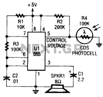
This circuit can be utilized as a light detector and potentially as a tool for individuals with visual impairments. The frequency of the oscillator is influenced by the level of illumination received by LDR4. The circuit operates by employing a...
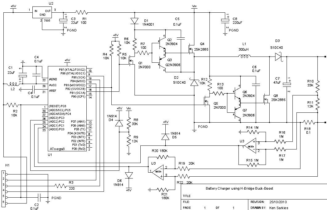
The buck-boost converter is valuable when the output and/or input voltages fluctuate significantly, necessitating the use of a buck converter at times and a boost converter at others. An example, which will be elaborated on in a future project,...

The audio mixer schematic proposed is developed around four amplifiers built inside the SSM2024 produced by Precision Monolithics Inc. (PMI) and is voltage-controlled (VR). The maximum VR voltage is 5.5 volts. The signal-to-noise ratio is 90 dB, and the...
The transformer is a 220V to 12V, 50Hz, and 3.6VA PCB type transformer. The model depicted is HRDiemen E3814056. Being encapsulated, it is isolated from external influences. A 250V 400mA glass fuse protects the circuit from damage caused by...
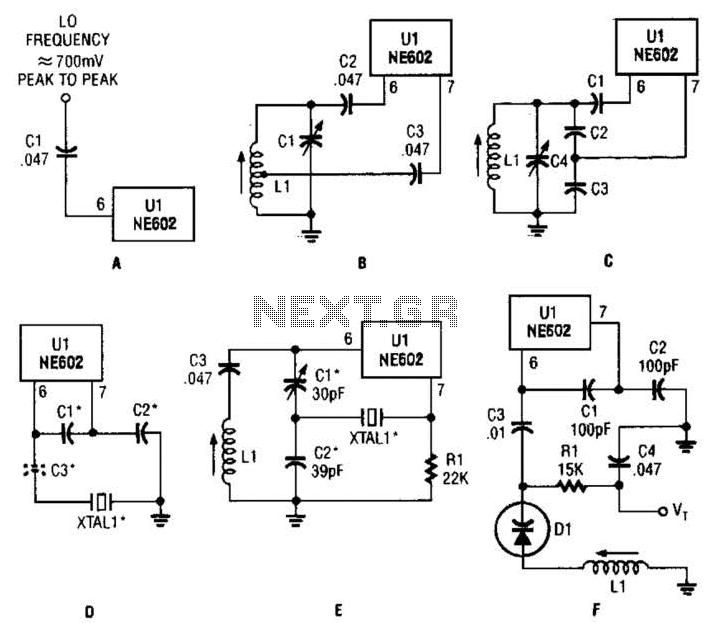
Any standard oscillator, such as a Colpitts or Hartley configuration, can be utilized to generate the local oscillator (LO) frequency required by the NE602. The NE602 is a versatile integrated circuit commonly used in radio frequency applications, particularly in mixer...