
matrix keypad pic microcontroller
The function readKeyboard() initializes the keypad scanning process and returns the character associated with the pressed key when a key press is detected. The scanning mechanism iterates through each row, setting each column high in turn. The state of the input pins is then checked to determine if any key is pressed. The function findKey() is called to map the row and column indices to their respective characters. If no key is pressed, a null character is returned.
The implementation of the findKey() function allows for customization of the characters associated with each key by modifying the return values based on the row and column inputs. This flexibility enables the design to accommodate various applications and user requirements.
Additionally, the seven-segment display integration is managed through the sevenSegmentDecoder() function, which translates the character inputs into the corresponding binary values required to illuminate the correct segments of the display. Each character is mapped to a specific hexadecimal value that represents the segments to be activated. This function can also be modified to include additional characters or change the segment representations as needed.
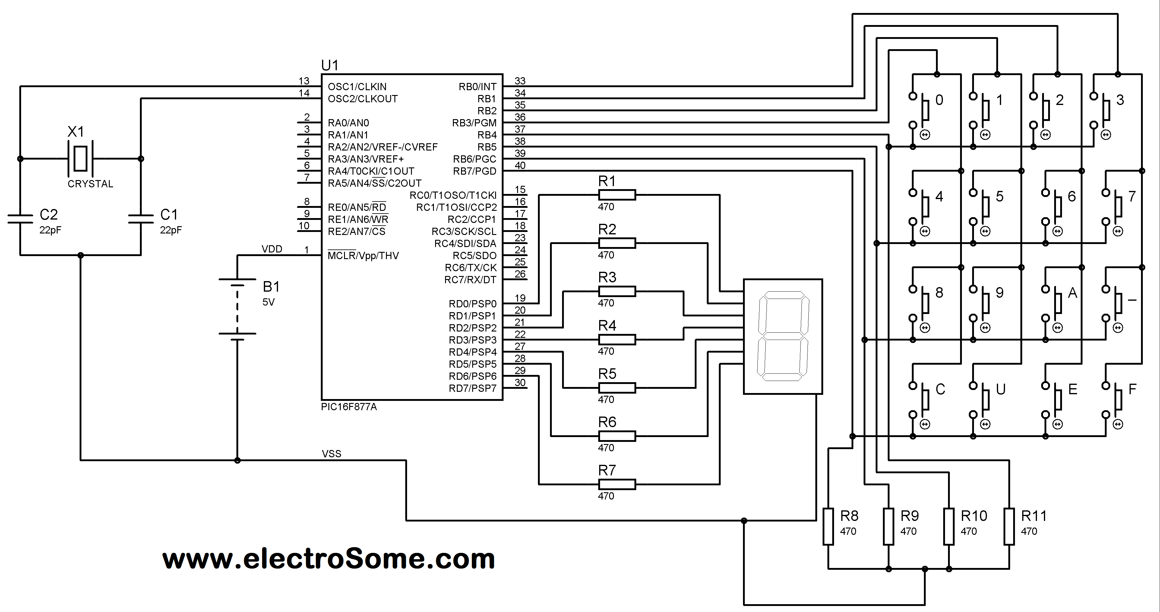
Overall, the combination of the matrix keypad and the seven-segment display offers a versatile solution for user input in embedded systems, allowing for efficient data entry and visual feedback. The design can be expanded or modified easily to suit a wide range of applications.Matrix Keypad is a very useful and userfriendly when we want to design certain applications like Calculator, Telephone etc. MatrixKeypad is made by arranging push button switches in rows and columns. Just imagine, if you want to interface a 4*4 (16 keys) matrix keypad with a microcontroller. In the straight forward way, you will need 16 pins of a microcontroller for that, but by using a simple technique we can reduce it to 8 pins. In the matrix keypad switches are connected in a special manner a shown in the figure below. Pressed keys can be detected by Scanning. For the sake of explanation, lets assume all column connections (Col1 Col4) are input pins and all row connections (Row1 Row4) are output pins. In the normal case (not scanning) all column inputs where in LOW (GND) state. For scanning keypad, Then each Row output (row1 row4) is scanned one by one. If any of the key belongs to first column is pressed, the Logic high signal from the Col1 will pass to that row.
Through we can detect the key. In this post I am explaining only about detecting one key at a time. For explaining the working I am using a 4*4 matrix keypad and the result is displayed in a Seven Segment Display. Matrix Keypad scanning is stopped as soon as any key press is detected and the Scanning is restarted if we need more inputs.
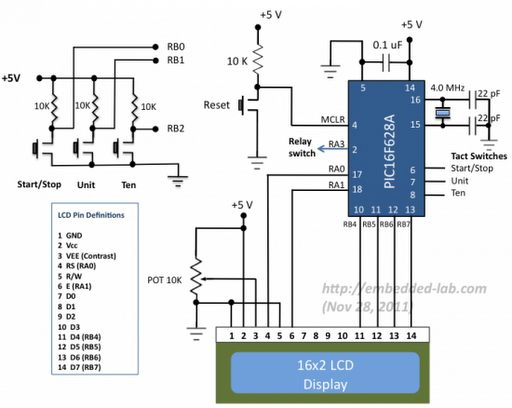
Matrix Keypad is connected to the PORTB of the PIC Microcontroller. Each column of the Matrix Keypad is connected to RB0 RB3 of the PIC Microcontroller, which are configured as output pins. While each row of the Matrix Keypad is connected to RB4 RB7 of the PIC Microcontroller, which are configured as input pins.
Here I am using 4*4 matrix keypad, having characters 0, 1, 2, 3, 4, 5, 6, 7, 8, 9, A, -, C, U, E, F. B` is replaced by -` and D` is replaced by U` because Seven Segment Display is used for displayingcharacters. B` will besimilarto `8 ² and D` will be similar to `0 ² when displayed in Seven Segment Display. For reading data for the Matrix Keypad, each column is made high and rows are scanned as I said above.
We use the function readKeyboard() to scan the Matrix Keypad and findKey() to find the pressed key. You can edit the function findKey() to change the character corresponds to each key of the Matrix Keypad. char readKeyboard() { unsigned int i = 0; for(i=0;i<4;i+) { if(i = 0) PORTB = 1; else if(i = 1) PORTB = 2; else if(i = 2) PORTB = 4; else if(i = 3) PORTB = 8; if(PORTB. F4) return findKey(i, 0); if(PORTB. F5) return findKey(i, 1); if(PORTB. F6) return findKey(i, 2); if(PORTB. F7) return findKey(i, 3); } return ` `; } This function initiates the keypad scanning and returns the character corresponds to the pressed key when a key press is detected.
It uses the function findKey() to find the character corresponds to a particular row and column. In this function space ( ) is used as the null character, which is returned when no key is pressed, you may change this according to your needs. char findKey(unsigned short a, unsigned short b) { if(b = 0) { if(a = 3) return `0`; else if(a = 2) return `1`; else if(a = 1) return `2`; else if(a = 0) return `3`; } else if(b = 1) { if(a = 3) return `4`; else if(a = 2) return `5`; else if(a = 1) return `6`; else if(a = 0) return `7`; } else if(b = 2) { if(a = 3) return `8`; else if(a = 2) return `9`; else if(a = 1) return `A`; else if(a = 0) return `-`; } else if(b = 3) { if(a = 3) return `C`; else if(a = 2) return `U`; else if(a = 1) return `E`; else if(a = 0) return `F`; } } This function returns the character corresponding to a particular row and column.
You may change characters corresponding to each key according to your need by editing this function. unsigned int sevenSegmentDecoder(char a) { switch(a) { case `0`: return 0x3F; case `1`: return 0x06; case `2`: return 0x5B; case `3`: return 0x4F; case `4`: return 0x66; case `5`: return 0x6D; case `6`: return 0x7D; case `7`: return 0x07; case `8`: return 0x7F; 🔗 External reference
Related Circuits
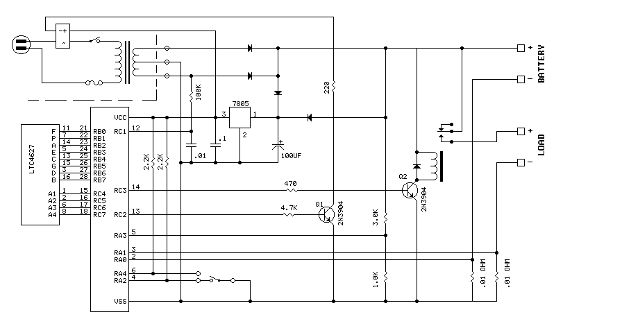
The PIC16F870 keeps track of battery voltage as well as both charging and discharging currents. It also drives the 4 digit display and switches the AC and load relays. The basic operation is as follows: While AC power is...

This version is V3.0, designed for TII use, featuring a stock FC ignition, a modified 24-2 style CAS, and a 3-bar MAP sensor. It has passed testing on the stimulator, indicating proper functionality. Future tests will be conducted on...
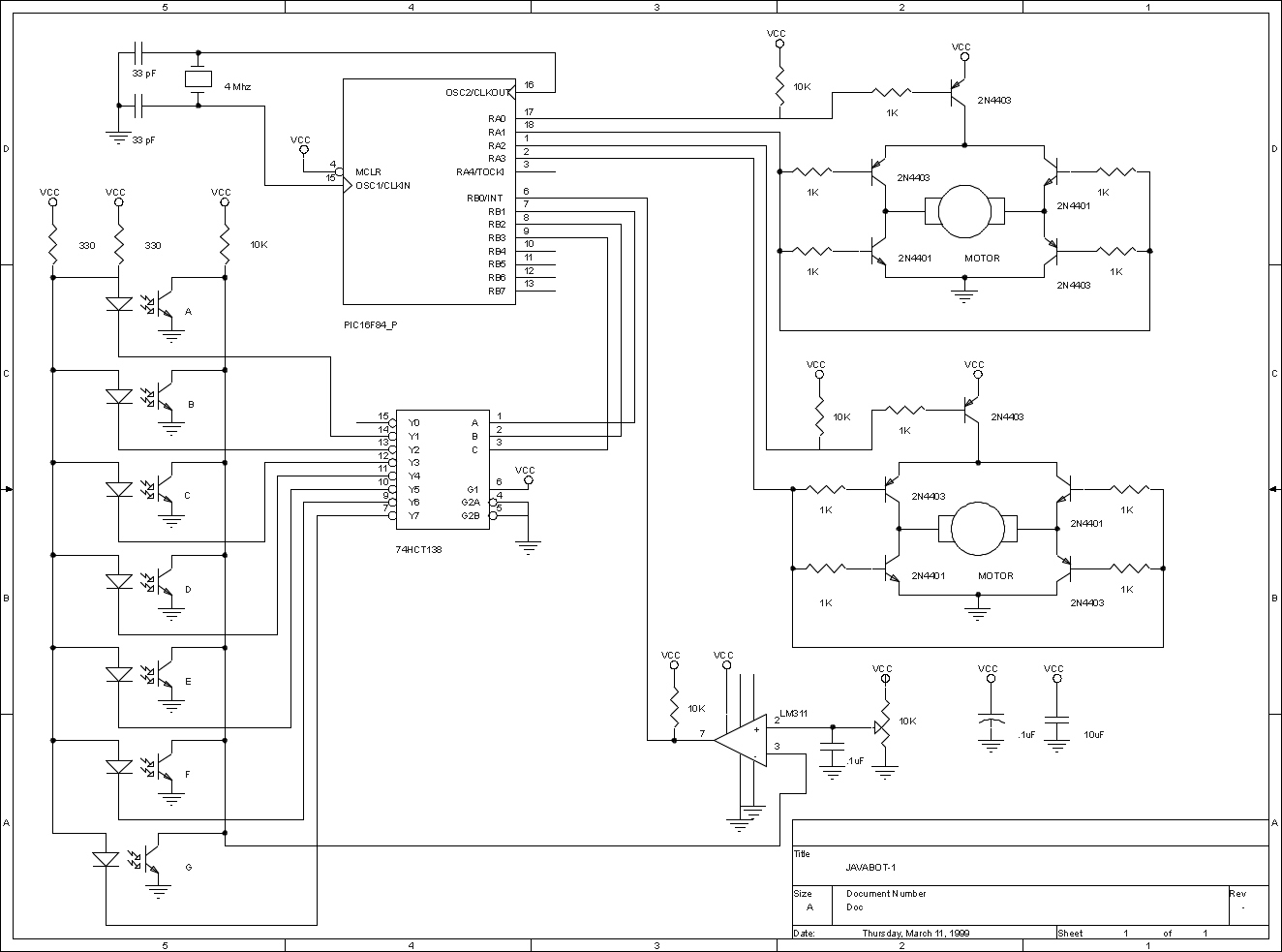
The JavaBot1 is a compact line-following robot engineered to trace a black line drawn on a dry erase board. It is specifically designed to navigate along very narrow curves. The JavaBot1 employs a differential drive mechanism, which allows it to...
This simple AVR programmer is capable of transferring hex programs to most ATMEL AVR microcontrollers. It is more reliable than many other simple AVR programmers available and can be constructed in a very short amount of time. This programmer...

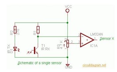
A passive high-pass filter has been added after the output of the operational amplifier (op-amp) to eliminate DC offset, with the op-amp powered by +12V and the negative supply at 0V. A feedback resistor (Rf) of 500K Ohms is...
A source code for a simple PIC-based digital timer is provided. The hardware for the project is not available; however, it will be demonstrated using a DIY PIC16F628A breadboard module and I/O board. The complete circuit diagram and firmware...
Warning: include(partials/cookie-banner.php): Failed to open stream: Permission denied in /var/www/html/nextgr/view-circuit.php on line 713
Warning: include(): Failed opening 'partials/cookie-banner.php' for inclusion (include_path='.:/usr/share/php') in /var/www/html/nextgr/view-circuit.php on line 713