
Whistle Responder Schematic circuit
The circuit design employs an electret microphone that converts sound waves into an electrical signal. The output from the microphone is fed into the first inverter (IC1A), which amplifies the signal to a usable level. The amplified signal is then routed to the second inverter (IC1B), where it passes through a band-pass filter. This filter is crucial as it allows only the desired frequency range (approximately 1.8 kHz) to pass while attenuating other frequencies, thereby reducing false triggering caused by background noise.
The output from the band-pass filter is then processed by the Schmitt trigger (IC1C). The Schmitt trigger is designed to provide a clean digital signal by converting the analog audio signal into a square wave, which is more suitable for digital processing. This square wave is then fed into a monostable multivibrator (IC1D), which generates a pulse of a fixed duration (two seconds) in response to the detected whistle.
Following the monostable multivibrator, the circuit transitions to an astable multivibrator configuration formed by IC1E and IC1F. This configuration generates a continuous square wave output at a frequency between 3 to 5 Hz, which is used to drive the transistor (Q1). The transistor acts as a switch, controlling the current flow to the buzzer (BZ1). When the transistor is activated, the buzzer produces an intermittent sound, effectively alerting the user to the detected whistle.
In summary, this circuit effectively combines audio amplification, frequency filtering, signal conditioning, and timing functions to create a responsive and reliable whistle detection system that provides audible feedback through an intermittent beeping sound.This device beeps intermittently for about two seconds when a person in a range of around meters emits a whistle. The first two inverters contained in IC1 are used as audio amplifiers. IC1A amplifies consistently the signal picked-up by the small electret-microphone and IC1B acts as a band-pass filter, its frequency being centered at about 1.8KHz.
The filter is required in order to select a specific frequency, the whistle`s one, stopping other frequencies that would cause undesired beeper operation. IC1C is wired as a Schmitt trigger, squaring the incoming audio signal. IC1D is a 2 second-delay monostable driving the astable formed by IC1E & IC1F. This oscillator generates a 3 to 5Hz square wave feeding Q1 and BZ1, thus providing intermittent beeper operation..
🔗 External reference
Related Circuits
Sawtooth wave generators using opamp are very common. But the disadvantage is that it requires a bipolar power supply. A sawtooth wave generator can be built using a simple 555 timer IC and a transistor as shown in the...

Cable and xDSL modems are increasingly popular, leading to a need for designs that interface with existing telephones at subscriber locations. The subscriber line interface circuit (SLIC) within the modem must ring the phone and provide loop current during...
The wireless FM transmitter circuit described here includes an additional RF power amplifier stage following the oscillator stage, which increases the power output to 200-250 mW. The wireless FM transmitter circuit functions by modulating audio signals onto a radio frequency...
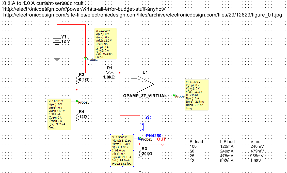
Exploring various methods for current sensing using standard operational amplifiers instead of specialized chips like the MAX4073T/F/H, which perform well but are relatively expensive. An article by Bob Pease discussing "error budgets" caught attention, particularly Figure Two of the...
The following circuit is a basic 555 square wave oscillator. Features include a 1 kHz tone, simple circuitry, a current limit of 200 mA, reduced inductive voltage, and a supply voltage range of 4.5 to 9 volts. Components used...
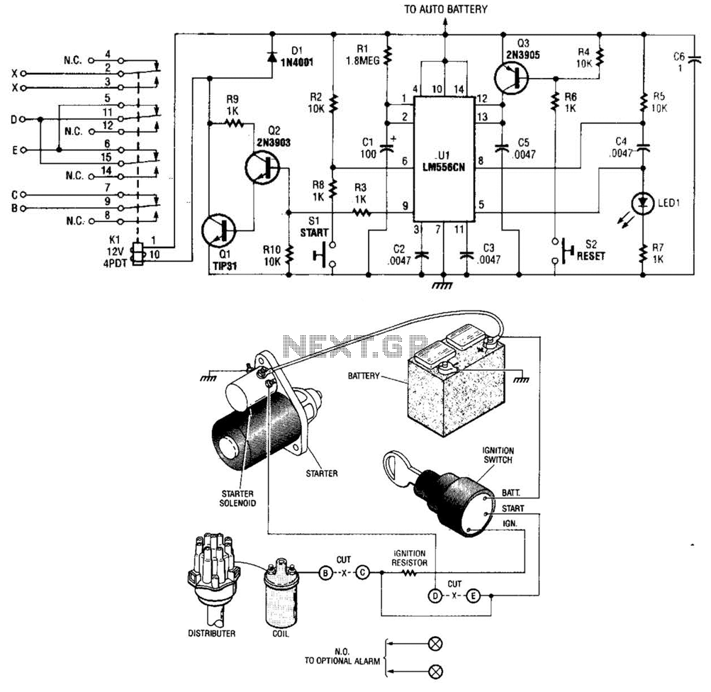
The automobile delayed kill switch operates on a straightforward principle. Upon exiting the vehicle, a hidden pushbutton switch is activated. Although no immediate effect is visible, after a preset duration, a relay engages and locks in place. This action...
Warning: include(partials/cookie-banner.php): Failed to open stream: Permission denied in /var/www/html/nextgr/view-circuit.php on line 713
Warning: include(): Failed opening 'partials/cookie-banner.php' for inclusion (include_path='.:/usr/share/php') in /var/www/html/nextgr/view-circuit.php on line 713