
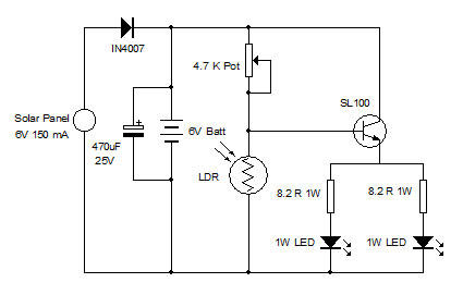
White LED Lamp with Solar Panel
The circuit design for a sequential timer using the IC555 timer includes several key components: the IC555 timer itself, resistors, capacitors, and relay drivers. The IC555 timer is configured in astable mode to generate a square wave output, which controls the timing of the motor's operation. The configuration involves selecting appropriate resistor and capacitor values to set the desired time intervals for the forward and reverse rotations of the motor.
In the astable configuration, the output frequency is determined by the formula:
\[ f = \frac{1.44}{(R1 + 2R2) \cdot C} \]
where \( R1 \) and \( R2 \) are the resistances connected to the discharge and threshold pins, and \( C \) is the timing capacitor connected to the ground. By adjusting these components, the time the motor runs in each direction can be finely tuned.
The output from the IC555 timer is connected to a relay driver circuit, which may include transistors or MOSFETs to handle the higher current required by the motor. When the timer output goes high, it energizes the relay, allowing current to flow to the motor in the forward direction. After the set time elapses, the relay de-energizes, stopping the motor. The output is then switched to reverse the motor's direction, and this process continues in a loop.
The design can also incorporate additional features such as manual overrides or safety mechanisms to prevent motor damage due to overheating or excessive load. The sequential timer can be expanded to control multiple motors or processes simultaneously, making it a versatile solution in both industrial and domestic applications. The simplicity of the IC555 timer makes it an accessible choice for implementing sequential control without the complexity of microcontroller programming, while still providing reliable and effective motor control.In most of the industrial processes it is required to rotate DC (or AC) motor forward and reverse for desired time. First motor rotates forward (clockwise) for some time (say 2 3 min) then it stops for some time. Again it rotates reverse (anticlockwise) for some time and rests. This process repeats every time when gets triggered. For example, in automated bottle filling plant, the bottles are moving on conveyor belt. When it comes under filler, the filler comes down (that means motor attached with mechanism rotates forward) then it fills the bottle (that means motor stops). Again it goes up (motor rotates reverse) and stops. As the next bottle arrives, the same process is triggered again. For moving filler up and down the time of rotating motor forward and reverse is calibrated and fixed.
Also the motor stop time is calibrated based on time required to fill the bottle. Another very good domestic application is washing machine. Once timer is set to wash cloths the motor automatically rotates forward and reverse for fixed time (10 15 sec) with small pause in between. So I can give thousands of such applications where there is a need to run motor forward stop reverse forward .
and so on. Now because this is sequential process we can use sequential timer. Sequential timer is widely used circuit in industries because in most of the industries all the processes are of chain reaction type. That means one process ends and it triggers next. The last process triggers first process when it ends. And thus the cycle continues. These sequence timers are micro controller based multi-functional and programmable. But here I have developed a sequential timer using simple IC555. So let us see how it is done These stages actually energize or de-energize relays that connect motor with the supply.
Let us see the block diagram of this sequential timer controlled DC motor. 🔗 External reference
Related Circuits
In this circuit, the 555 timer is utilized in an innovative manner as a voltage-controlled switch. The widely used NE555 can perform effectively in various applications. The 555 timer, a versatile integrated circuit, is commonly employed in timer, delay, pulse...
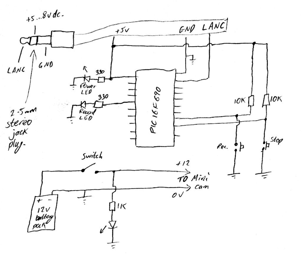
Inexpensive PIC-controlled helmet camera utilizing Sony LANC, suitable for extreme sports. This guide will demonstrate how to create an affordable helmet camera. The proposed electronic schematic involves a PIC microcontroller interfaced with a Sony LANC (Local Application Control Bus) to...
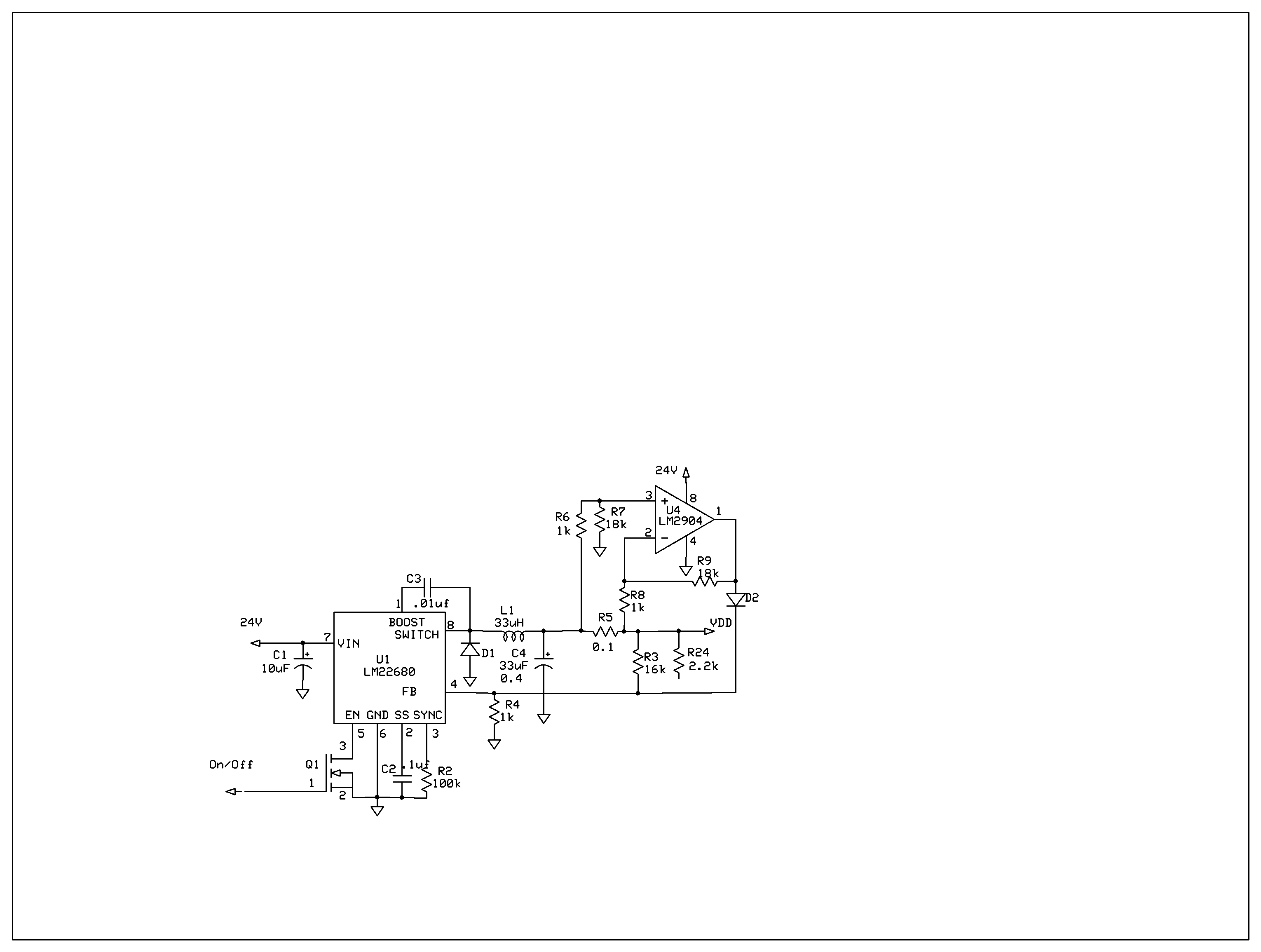
The product requires a voltage-controlled, current-limited power supply. Various switcher chips have been used with an op-amp to provide feedback for a current sense voltage to the feedback pin. Currently, an LM22680 is in use, but it has shown...
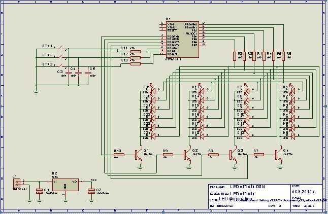
This project I made for my little daughter. It is 24 channel light illumination. The schematic is very simple 24 LEDs, 1 MCU and some additional components. The main principle is dynamic indication, which is usually implemented for control...
This is a 0 - 6 MHz DDS VFO controlled by a PIC16F84 (or C84). The VFO is separated into two modules, the DDS module and the controller module. The PCB layout (double sided) for the DDS module is...
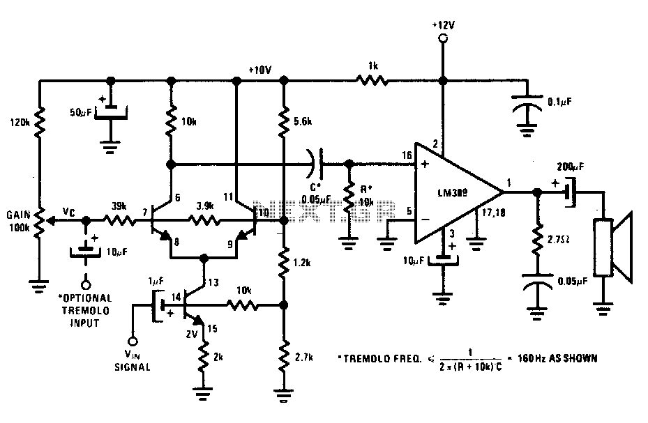
The transistors create a differential pair with an active current-source tail. This configuration, referred to as a variable-transconductance multiplier, produces an output that is proportional to the product of the two input signals. The multiplication effect arises from the...