
pic controlled helmet camera using pic16f690
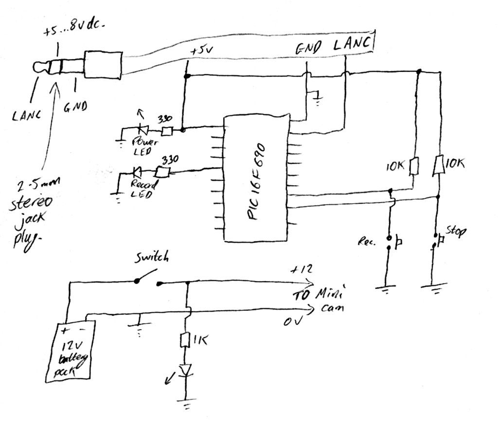
The proposed electronic schematic involves a PIC microcontroller interfaced with a Sony LANC (Local Application Control Bus) to control a helmet-mounted camera. The design is aimed at extreme sports enthusiasts who require a lightweight and cost-effective solution for capturing high-quality video footage during activities such as biking, skiing, or skateboarding.
The core of the circuit utilizes a PIC microcontroller, which is programmed to send commands to the camera via the LANC protocol. The microcontroller can be powered using a small lithium polymer battery, ensuring that the overall weight remains minimal. The LANC interface consists of a simple serial communication line that allows for commands such as start, stop, and zoom to be transmitted to the camera.
In addition to the microcontroller and power supply, the circuit may include a few supporting components such as resistors, capacitors, and possibly a MOSFET for switching the camera on and off. A user interface, which could consist of buttons or a small joystick, allows the user to control the camera functions conveniently while wearing the helmet.
The entire assembly should be enclosed in a robust, waterproof housing to protect the electronics from the elements, ensuring durability during extreme activities. Proper mounting techniques must be employed to securely attach the camera to the helmet, allowing for stable video capture without obstructing the user's vision.
This design not only provides an affordable solution for recording extreme sports but also allows for customization and expansion, such as integrating additional sensors or features, thus enhancing the overall functionality of the helmet camera system.Cheap PIC controlled Helmet Camera using Sony LANC (Good for Extreme Sports) This Instructable will show you how to make a cheap Helmet Camera which can be.. 🔗 External reference
Related Circuits
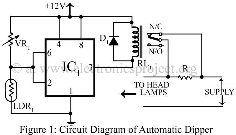
An automatic dipper for vehicles utilizing a timer IC NE555 and a light-dependent resistor (LDR) to control the headlight intensity of vehicles. This circuit diagram serves as a reference for various automobile projects. The automatic dipper circuit employs the NE555...
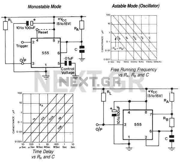
The 555 is a highly stable device for generating accurate time delays or oscillation. Additional terminals are provided for triggering or resetting if desired. In the time delay (monostable) mode of operation, the time is precisely controlled by one...
Power and serial communications are provided by the FTDI USB to RS232 converter chip. No additional setup is required; simply connect the USB cable from the computer to the board, and a new serial COM port will be installed...
When you use microcontrollers in your designs, sometimes you face a problem how to show user required data. Several LEDs, 7 segment display or LCD module can be solution. But if you must show a lot of information simultaneously,...
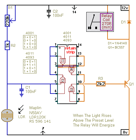
The first circuit energizes the relay when the light rises above the preset level. The second circuit energizes the relay when the light falls below the preset level. The two circuits are practically identical. The only difference between them...
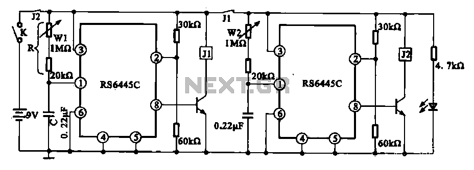
The timing integrated circuit (IC) RS6445C functions as a blocking oscillator. It features two segments, WI and W2, which are utilized to adjust the working time and the closure time. These adjustments can be continuously set within a range...