
white light led driver with
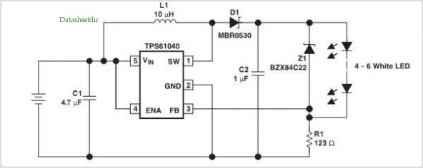
The circuit design utilizing the TPS61040 white light LED driver is an efficient solution for providing consistent and gradual illumination for white LEDs in portable devices. The TPS61040 is a step-up (boost) converter that is specifically engineered to drive LEDs with a regulated constant current, ensuring uniform brightness across multiple LEDs.
The circuit begins by taking a low voltage input, which can range from 1.8 V to 6 V, and boosts it to the necessary voltage levels required to drive the LEDs. This feature is particularly beneficial for battery-operated devices, as it allows for the efficient use of power from various battery configurations, including alkaline, NiMH, and Li-Ion cells.
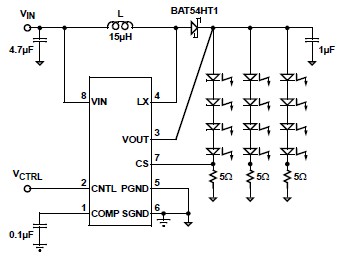
The resistor R1 plays a crucial role in setting the output current flowing through the LEDs. By selecting an appropriate value for R1, the desired constant current of 101 mA can be achieved, which is optimal for driving up to six white LEDs in series. This configuration not only simplifies the design by eliminating the need for a microprocessor but also enhances reliability by reducing potential points of failure.
The gradual illumination feature is implemented by controlling the switching frequency and duty cycle of the TPS61040, which can be adjusted to create a soft start and soft stop effect when powering the LEDs on and off. This approach minimizes sudden changes in brightness, leading to a more aesthetically pleasing user experience.
Overall, the TPS61040 circuit design represents a robust solution for LED driving applications, combining efficiency, simplicity, and effective current regulation to meet the demands of modern portable electronic devices. For further technical details and specifications, the TPS61040 data sheet (SLVS413) should be consulted.Many consumer products using white light LEDs for illumination and backlighting provide gradual LED illumination at turnon and turnoff. This gradual illumination is usually achieved with the aid of a Microprocessor that provides PWM dimming control.
This circuit uses the Texas Instruments TPS61040 white light LED Driver to provide gradual illumina tion at turnon and turnoff without the use of a Microprocessor The following circuit generates a 101mA constant current to drive up to 6 white LEDs for portable applications such PDAs and digital cameras. The input operating range is 1. 8 V to 6 V, which covers two-cell alkaline and NiMh inputs (1. 8 V to ~3 V), three-cell alkaline and NiMh inputs (2. 7 V to ~4. 8 V), and single-cell Li-Ion inputs (3 V~4. 2 V). This boost converter uses R1 to set a constant current through the LEDs A detailed description of this circuit CAN be found in the TPS61040 data sheet ( SLVS413 ).
🔗 External reference
Related Circuits
I ride my bike allot at night and sometimes I'm not sure if people can see me. This circuit will flash an incandescent light that you can purchase from Radio Shack. Adjust the VR's for your flash requirements and...
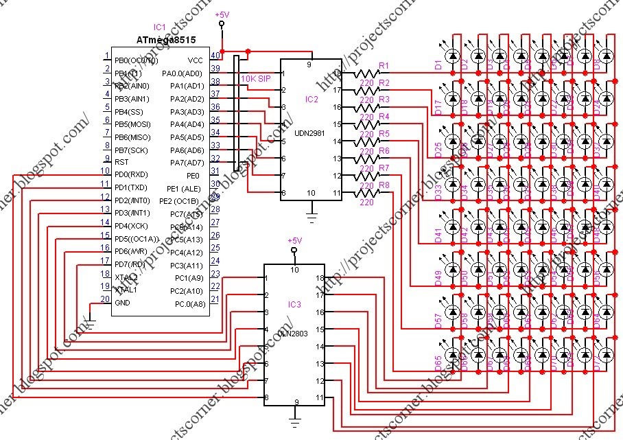
This project involves a scrolling LED display composed of 64 LEDs arranged in a matrix configuration. The anodes of the LEDs are driven by a driver IC, UDN2981, while the cathodes are controlled using the ULN2803. An Atmega8515 microcontroller...
This circuit enables a smaller control voltage to inversely and linearly control a larger output voltage (Vo). Additionally, the supply voltage (Vsp) for the operational amplifiers can be lower than the output voltage, allowing the circuit to theoretically control...
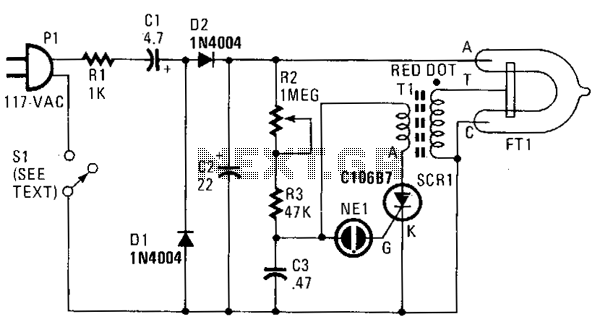
In this strobe light, two circuits are required: one circuit charges a capacitor to create a 320 V DC potential between the cathode and anode of the flashtube, while the other circuit generates bursts of approximately 4000 V to...
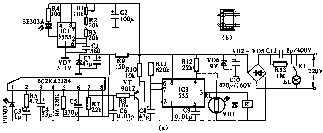
This circuit utilizes the KA2184 infrared receiver ASIC for an infrared remote control dimmer light application, as depicted in the schematic. The infrared signal is generated by a pulse generator using an NE555 timer integrated circuit. The NE555 produces...
A simple white LED driver schematic can be created using the EL7513 constant current boost regulator, which is specifically designed for driving white LEDs. This driver can manage 4 LEDs in series or up to 12 LEDs in a...