
wi fi interfacing with lpc2148 arm7 primer

The circuit design for interfacing the Wi-Fi module with the LPC2148 Primer Board involves several key components and connections. The LPC2148 microcontroller serves as the central processing unit, managing data flow and communication protocols. The MAX232 chip is employed to convert the TTL level signals from the microcontroller to RS232 level signals suitable for communication with the Wi-Fi module. This conversion is essential for ensuring compatibility between the microcontroller and the Wi-Fi module.
The UART0 interface on the LPC2148 is configured to operate at a baud rate of 9600, which is a standard speed for serial communication. The configuration involves setting the appropriate registers in the LPC2148 to ensure that data is transmitted and received correctly. The SBUF register is utilized for data storage during transmission and reception processes. The serial interrupt feature of the microcontroller allows for efficient handling of incoming data, enabling the microcontroller to respond to data as it is received without continuous polling.
Power supply considerations are crucial for the stability of the circuit. The LPC2148 requires a +3.3V supply, while the Wi-Fi module typically operates at +5V. Care should be taken to ensure that these voltage levels are correctly applied to avoid damage to the components. The connection between the LPC2148 and the PC via a serial cable allows for monitoring and debugging of the data transmission, using software such as HyperTerminal to visualize the data flow.
In summary, this circuit effectively demonstrates the integration of a Wi-Fi module with a microcontroller using UART communication, enabling wireless data transmission and reception. Proper setup, including power supply and software configuration, is essential for successful implementation.Circuit shows how to interface the Wi-Fi with microcontroller. The Wi-Fi module continuously transmits or receives serial data (RS232 protocol) through internet without wires. It delivers the received data and receives the data to be transmitted to and from a host system through a host controller interface (HCI).
The most popular host controller interface today is either a UART or a USB. Here, I will only focus on the UART interface; it can be easily show how a Bluetooth module can be integrated on to a host system through a UART connection. Transmit or Receive data over internet with LPC2148 Primer Board by using Wi-Fi module through UART0.
The message communication is done in internet or mobiles using Wi-Fi module through MAX232 into the SBUF register of LPC2148 microcontroller (refer serial interfacing with LPC2148). The serial data from the Wi-Fi receiver is taken by using the Serial Interrupt of the controller. The UART0 pin lines are used to transmit & receive operations in LPC2148 Primer Board. The Interfacing Wi-Fi module with LPC2148 program is very simple and straight forward, which send or receive a message in LPC2148 Primer Board through Wi-Fi module by using UART0.
Some delay is occurring when a single data is transmitted or received through UART0. C programs are written in Keil software. The baud rate of microcontroller is 9600. To compile the C code you need the KEIL software. They must be properly set up and a project with correct settings must be created in order to compile the code. To compile the above code, the C file must be added to the project. In Keil, you want to develop or debug the project without any hardware setup. You must compile the code for generating HEX file. In debugging Mode, you want to check the port output without LPC2148 Primer Board. Give +3. 3V power supply to LPC2148 Primer Board; connect the +5V adapter with Wi-Fi module which is connected with the LPC2148 Primer Board.
There are two Wi-Fi modules are required. One is connected with LPC2148 Primer Board; other one is connected with PC. First connect the serial cable between LPC2148 Primer board & PC. Then open the Hyper Terminal screen, select which port you are using and set the default settings. Now the screen should show some text messages. If the messages are correctly displayed in Hyper Terminal, then only connect the Wi-Fi modules in LPC2148 Primer Board UART0 & PC. If you are not reading any data from UART0, then you just check the jumper connections & just check the serial cable is working.
Otherwise you just check the code with debugging mode in Keil. If you want to see more details about debugging just see the videos in below link. 🔗 External reference
Related Circuits
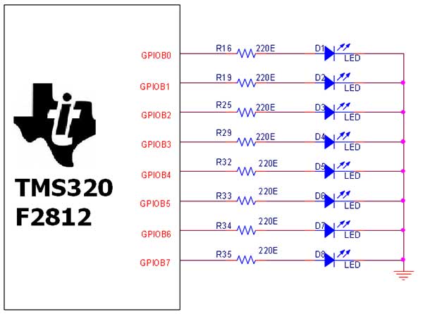
The TMS320F2812 Evaluation Board is specifically designed for developers in the digital signal processing (DSP) field, as well as for beginners. The F2812 kit is structured to allow easy access to all the features of the DSP. The TMS320F2812...
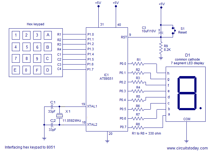
Interfacing a hex keypad to an 8051 microcontroller. The AT89S51 is utilized in this setup. A circuit diagram and assembly language program are included. A testing video is also provided. The interfacing of a hex keypad with the AT89S51 microcontroller...
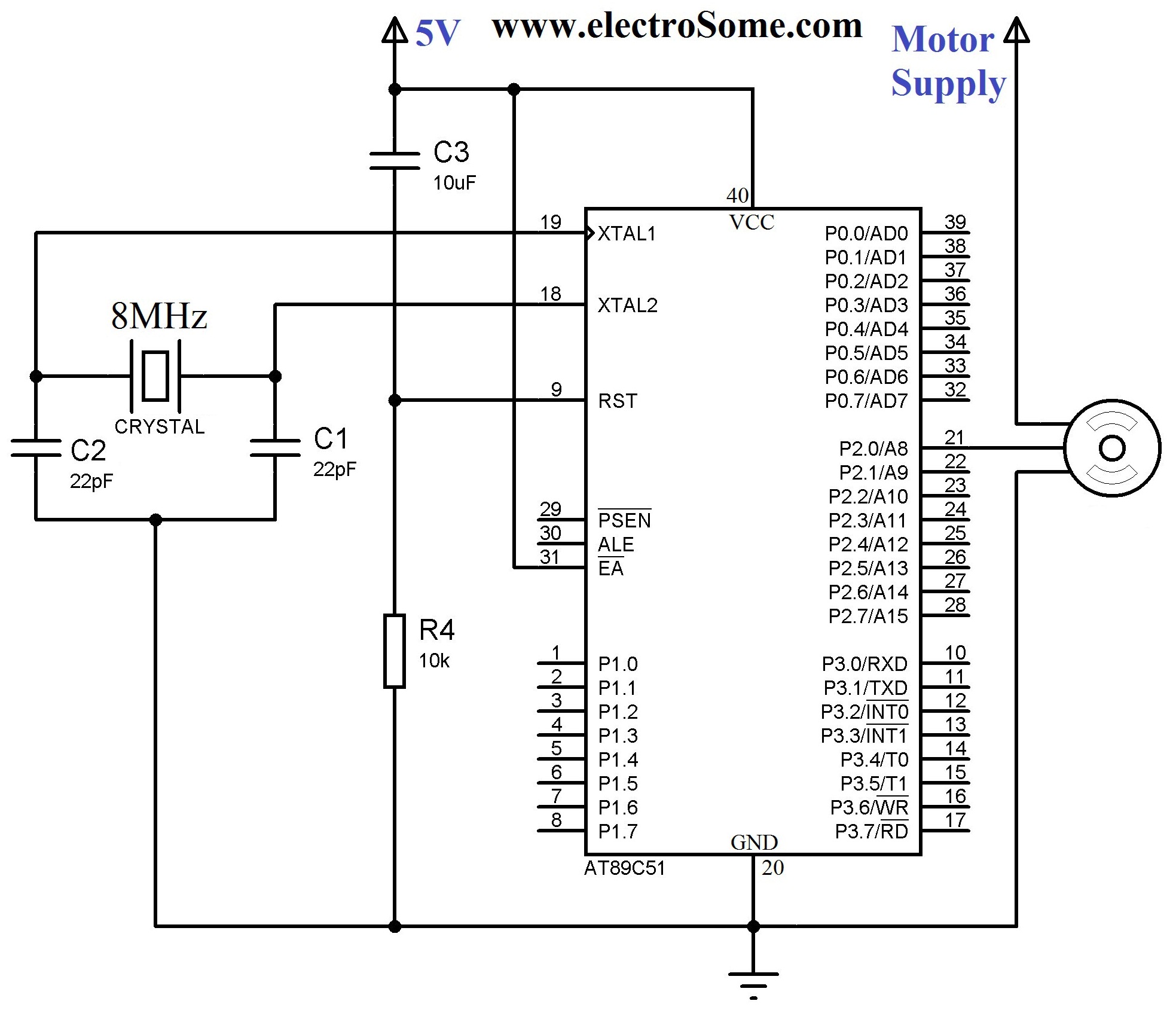
A servo motor employs a servo mechanism, which is a closed-loop system that utilizes position feedback to accurately control the angular position of its shaft. Stepper motors, which operate as an open-loop system, can also achieve precise angular control,...
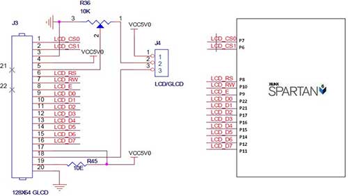
The Spartan-6 board features a 2x16 LCD, as illustrated in the accompanying figure. This 2x16 character LCD interface card supports both 4-bit and 8-bit modes, and it includes a facility for contrast adjustment via a trim potentiometer. In the...
LCD initializations in 8051 C programming involve understanding the logic behind serial communication, including the duration of SIG pulse transmission and the necessary delays. These statements inform the compiler that a 16x2 LCD is connected to the defined pins...
.jpg)
Many designers today are implementing embedded systems that require low-cost non-volatile memory. Microchip has addressed this need with a full line of serial EEPROMs, in a variety of memory configurations, using the industry-standard 2- or 3-wire communication protocols. The...