
interfacing ultrasonic distance sensor ascii pic microcontroller
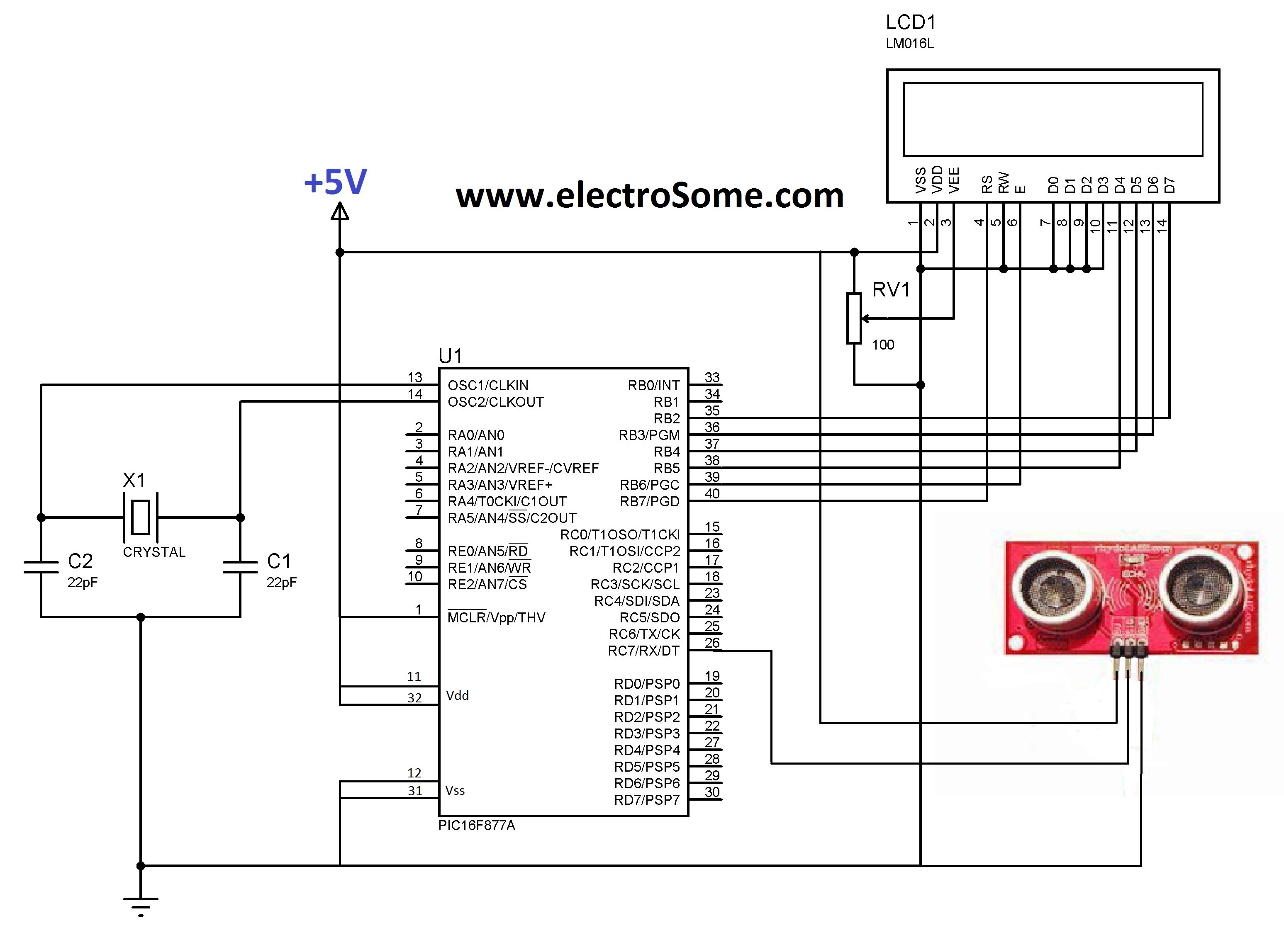
The 8051 microcontroller's interaction with an LCD display involves a series of initialization steps, where specific commands are sent to the LCD to configure it for display operations. The LCD typically operates in a 4-bit or 8-bit mode, and the microcontroller must be programmed to send the appropriate control signals to set the mode, clear the display, and position the cursor.
In serial communication, the timing of the SIG pulse is crucial. The duration of the pulse and the delay between pulses must be carefully calculated to ensure proper communication between the microcontroller and the LCD. This timing is generally defined in microseconds and must adhere to the specifications of the LCD being used.
The TRIS and PORT registers play a vital role in determining how the microcontroller interacts with the LCD. The TRIS register configures each pin as either an input or an output, while the PORT register is used to set the high or low state of those pins. This flexibility allows the LCD to be connected to different pins on the microcontroller without altering the fundamental program structure.
When integrating an ultrasonic sensor, the trigger and echo pins must be correctly assigned in the program. The trigger pin is activated to send an ultrasonic pulse, while the echo pin receives the reflected signal. The time taken for the echo to return is measured, and using the speed of sound, the distance can be calculated. The data format sent by the sensor is typically in ASCII, allowing for easy interpretation of the distance measurement. Each digit of the distance is sent separately, facilitating straightforward parsing by the receiving microcontroller or device.
In summary, the integration of an LCD display and ultrasonic sensor with an 8051 microcontroller requires careful consideration of initialization routines, timing for serial communication, and the proper configuration of registers to ensure accurate and effective operation.LCD initializations in 8051 C programming words What is the logic behind the serial communication As in, how long should the SIG send out pulses and what should the delay be These statements are used to tell the compiler that a 16X2 LCD is connected to the above defined pins and the LCD display is accessed using Lcd_ etc functions . Please go to this link to do this in 8051 using keil c RB is used instead of PORT register and TRIS itself a register. TRIS register is used to set the direction of each pins of that port while PORT register is used to set the status of each pin of that port . Compiler needs these registers during Building process, since LCD can be connected to any of the pins of the microcontroller.
Please try it yourself. arduino has all the required built in libraries so just replace the functions used in this program. to arduino functions. it will work. I already have ultrasonic sensor with echo and trigger pins instead of SIG pin. Can i know how micropic program should be changed according to echo and trigger pins. I think. when you provide trigger signal it sends an ultrasonic burst and gives echo signal when the ultrasonic burst receives back . So to calculate distance you should use the equation Distance = time * velocity where velocity is a constant.
how does the sensor send the data. i mean in what format. say the distance is 123. 4 cm, then ll it send the ASCII of 123. 4 separately. like ASCII of 4, then. `, then ASCII of 3 etc. 🔗 External reference
Related Circuits
This circuit is designed to serve as a programmable LED display for various applications. It features an 8 x 32 LED dot matrix interfaced with a Xino (or Arduino). In addition to the display, the circuit includes two buttons...

The circuit depicted in the schematic utilizes zero-drift operational amplifiers (LTC1250 and LTC1050) along with a precision instrumentation switched capacitor block (LTC1043). This design achieves exceptional DC accuracy down to microvolt levels. The choice of this method over a...
The following are detailed schematics for the QScreen Controller. The QScreen Controller integrates an embedded computer utilizing the 68HC11 microcontroller, along with a touch panel and an LCD (liquid crystal display) graphic user interface (GUI) that is well-suited for...
Dew (condensed moisture) adversely affects the normal performance of sensitive electronic devices. A low-cost circuit described here can be used to switch off any gadget automatically in case of excessive humidity. At the heart of the circuit is an...
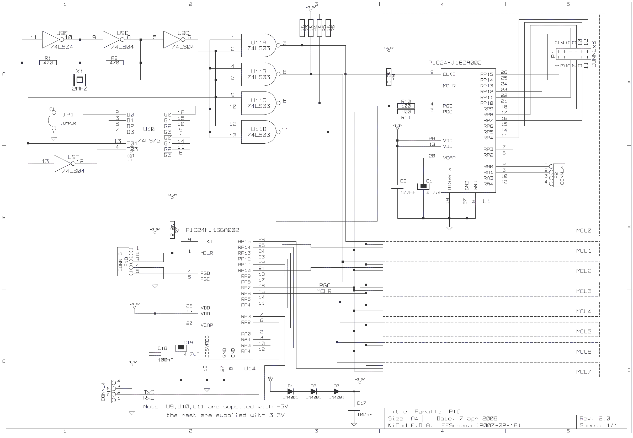
The purpose of this project is to construct a computer that utilizes the combined computational power of multiple microcontrollers (MCUs). All MCUs collaborate to solve a single problem. This computer is classified as a parallel processing machine, and the...
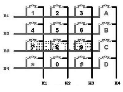
This includes an interface that is simple enough for mastery, as the keypad supports input facilities commonly used in Man-Machine Interface (MMI) applications. For example, various types of keypads can be found in the market. This discussion will focus...
Warning: include(partials/cookie-banner.php): Failed to open stream: Permission denied in /var/www/html/nextgr/view-circuit.php on line 713
Warning: include(): Failed opening 'partials/cookie-banner.php' for inclusion (include_path='.:/usr/share/php') in /var/www/html/nextgr/view-circuit.php on line 713