
MSF detector - turning the radio signal into data
The MSF transmitter operates by sending precise time data in a structured manner, utilizing a 60 kHz carrier frequency. The timing circuit's implementation of negative logic allows for clear differentiation between transmitted data bits, with the ON state indicating a 'zero' and the OFF state representing a 'one'. This method relies on the accuracy of the carrier drop, which is designed to be distinct, minimizing confusion that may arise from signal fading.
Signal reception can be enhanced through the use of a BFO, which effectively shifts the signal from the noisy DC region into a more manageable audio spectrum. This approach is particularly beneficial as it allows for the application of filtering techniques that can significantly improve the overall signal quality. When constructing a mixer circuit, careful attention must be paid to the selection of components, such as the NE602 mixer and the NE567 PLL, to ensure optimal performance.
In scenarios where a BFO is not available, alternative methods such as using a 455 kHz IF transformer can be employed. The design of the audio bandpass filter, while not strictly necessary, can provide additional clarity to the received signal, particularly in environments where signal strength may vary. All connections should be made with precision to ensure the integrity of the AGC voltage, which is crucial for maintaining consistent performance of the timing circuit.The MSF transmitter sends time data bit-by-bit over the 60 seconds of each minute by dropping the 60 kHz carrier. It`s a basic CW signal [1]. Two bits are transmitted every second by modifying the length and number of carrier drop(s) per second (see the second article in this series).
As is often the case in timing circuits a negative logic is use d. When the carrier is ON the data being sent is a `zero` and when the carrier off it is a `one`. It is the drop in career that is accurately timed i. e. the ON to OFF state rather than the OFF to ON state. I suppose dropping the carrier (ON to OFF) is a clearer transition than the OFF to ON transition, as fading might confuse the exact ON transition but the carrier going fully OFF is quite distinct. Reading the data sheet from the NPL it appears that they do more than key the carrier ON and OFF to get the precise signalling.
This may be because the high Q antenna / output circuit will `ring` for too long after the transmitter keys off. They imply that the ON / OFF data is a combination of data pulse and actual switching of power to the antenna system [1].
In principle we can take the changing voltage from the receivers automatic gain control (AGC) i. e. the S-meter circuit as the basis of the data detection signal. The S-meter voltage can be feed into a comparator / trigger to convert the change in signal strength into logic level (0 and 5V) data pulses. If the MSF signal is very steady and strong (i. e. if you are relatively near to the transmitter) then this will work well. This is shown at the top of the first picture. A little bit of hysteresis built into the comparator circuit will help to stop `chattering` at the transition edges at switch ON and at switch OFF.
The main problem is when the signal strength is weak or fading. When this happens the comparator will have problems because the transition point derived from the AGC voltage will be changing and so we won`t be able to detect the data reliably. You can see this in the bottom of the first picture. This problem is nicely discussed in the section on `data communications` in the latest RSGB handbook [2].
A much better way of detecting the MSF CW signal is to use a beat frequency oscillator (BFO) on the receiver and detect the audio tone that is created, rather than try and monitor the changing signal strength. From a signal processing point of view you are taking the signal away from the AGC `DC` region, where there is a lot of noise (drift and low frequency noise) and moving it into the `audio` spectrum where simple filters can dramatically improve the S/N ratio.
If you don`t have a BFO (CW or SSB) on your receiver (e. g. if you are using an old AM radio) you need to make up a mixer circuit that will take the IF o/p of the receiver (455 kHz) and `mix` it with a local oscillator frequency to produce an audio product. I used an old 456 kHz crystal to make a stable local oscillator (LO) and fed this into a NE602 mixer to make up a product detector.
The o/p is the difference ca. 456. 196 - 455. 000 kHz = 1. 196 kHz, a tone which I then feed into a simple phase locked loop (PLL) (NE567) tone decoder [3, 4]. If you can`t get hold of a 456 KHz crystal, you can use a 455 IF transformer (de-tuned by ca. 1 kHz) as a simple oscillator coil and use the NE605 internal LO circuitry, see diagram. I also used a two op-amp audio band pass filter which I put between the mixer and the PLL tone decoder (as indicated on the diagram) to get better signal to noise ratios but I don`t think it is really needed for the UK MSF signal strength. To get a decent signal for the BFO mixer you will need to wire into the IF of the radio. You can do this on the very last IF transformer; find the AM germanium detector diode which is usually directly on the output of the last IF transformer (don`t remove it as its also used to generate the AGC voltage) using a piece of miniature coax and connect be
🔗 External reference
Related Circuits
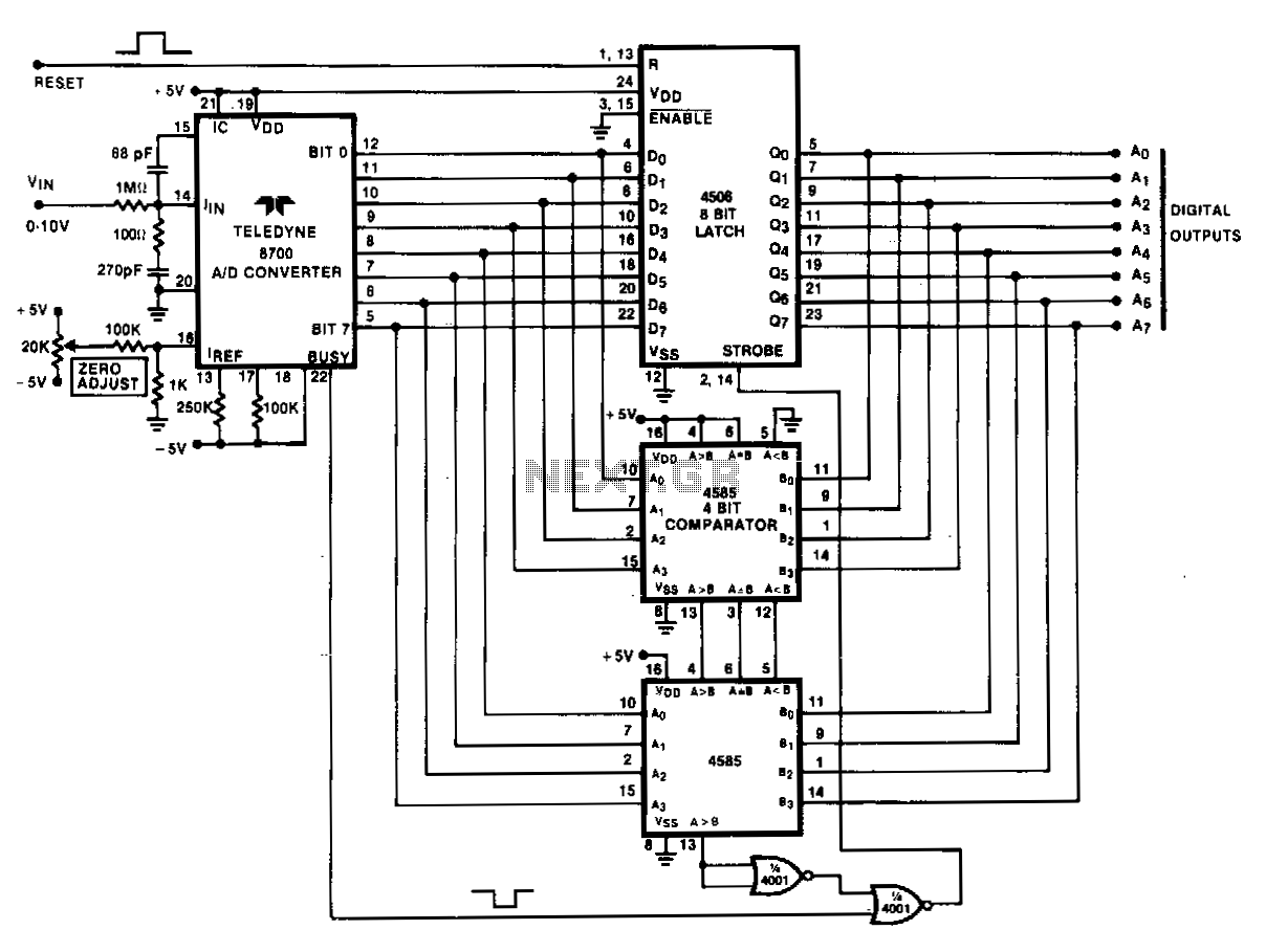
Analog peak detection is achieved by repeatedly measuring the input signal with an A/D converter and comparing the current reading with the previous reading. If the current reading is larger than the previous one, the current reading is stored...
Information about building a small radio transmitter, which has a PCB measuring 1.75" x 2.5" (45mm x 68mm) and has a range of approximately 30 yards. The documentation states that the frequency range is 100-108 MHz, but it has...
This is a simple and easy-to-build gold detector circuit. The circuit is capable of sensing gold, metal, or coins from a distance of approximately 20 cm, depending on the size of the object being detected. It oscillates at around...
This is a simple hardware computer interface and Linux program that can be used to control the most commonly used buttons on any consumer Family Radio Service (FRS) or General Mobile Radio Service (GMRS) radio. There are 22 available...
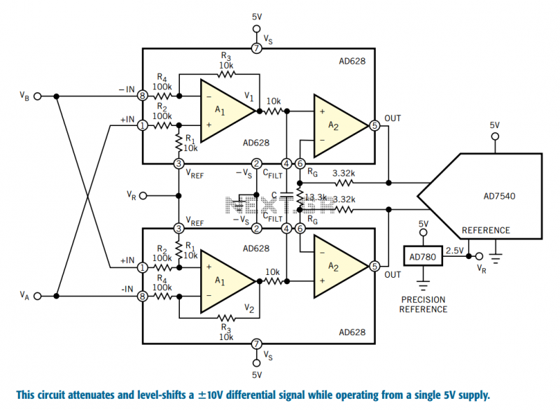
Designers who build equipment for the industrial market share a widespread problem. At one extreme, they must build equipment that supports ±10V bipolar voltages, often riding on a high common-mode level, a requirement enforced by 30 years of legacy...
This circuit was designed to detect when a call is incoming in a cellular phone (even when the calling tone of the device is switched-off) by means of a flashing LED. The device must be placed a few centimeters...