
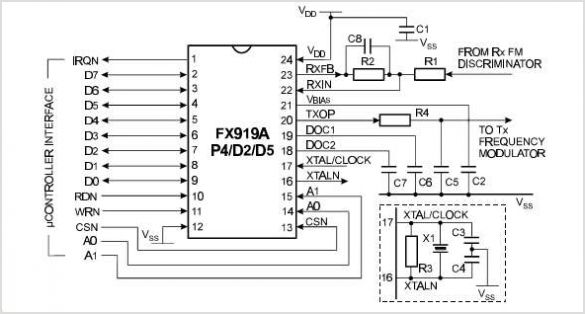
FX919A 4-Level FSK Modem Data Pump
The FAN7601 is a sophisticated device that integrates several essential features for efficient power management in electronic circuits. The BCDMOS technology utilized in the FAN7601 allows for high-performance operation with reduced power consumption, making it suitable for applications requiring reliability and efficiency. The burst mode operation is particularly advantageous in scenarios where the load varies significantly, as it enables the controller to minimize energy usage when demand is low.
The startup switch plays a crucial role in enhancing the efficiency of the startup process. By reducing the losses typically associated with the startup phase, the FAN7601 ensures that the system can achieve operational readiness with minimal energy expenditure. This feature is particularly beneficial in applications where energy efficiency is paramount.
In terms of safety and reliability, the latch protection pin provides an essential safeguard against potential faults, such as over-voltage conditions. The internal over-voltage protection mechanism ensures that the IC automatically shuts down when the voltage exceeds 19V, thereby preventing damage to the system. The thermal shutdown feature further enhances the reliability of the device by protecting it from overheating, which can lead to catastrophic failures.
The adjustable soft start function is another critical aspect of the FAN7601, allowing designers to customize the ramp-up time of the output voltage. This feature aids in reducing inrush current during startup, which can be detrimental to both the power supply and the connected load. By controlling the soft start duration, the designer can mitigate the risk of voltage spikes that may otherwise occur during the initial power-up phase.
Overall, the FAN7601 is a versatile and efficient PWM controller that incorporates advanced features aimed at optimizing performance and enhancing system reliability in various power supply applications. Its design is well-suited for integration into modern electronic systems that demand high efficiency and robust protection mechanisms.This application note describes the operation and features of the FAN7601. This device is a BCDMOS programmable frequency current mode PWM Controller which is designed for off-line adapter applications and auxiliary power supplies. To reduce power loss at light and no load, the FAN7601 operates in burst mode and it includes a start-up Switch to re
duce the losses in the start-up circuit. Because of the internal start-up Switch and burst mode oper- ation, it is possible to supply an output power of 0. 5W with under 1W input power when the input line voltage is 265V. On no load condition, input power is under 0. 3W. The FAN7601 offers a latch protection pin for the protection of the system e. g. over voltage protection and/or thermal shutdown. The internal over voltage protection function shuts down the IC operation when the supply voltage reaches 19V.
In addition, a soft start function is provided, and the soft start time CAN be varied. Figure 1 shows a block diagram for the 🔗 External reference
Related Circuits
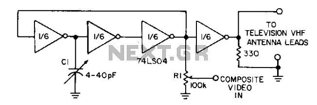
Three gates of a 74LS04 form the oscillator circuit. Capacitor C1 allows fine frequency adjustment to a specific television channel and helps stabilize the circuit. Potentiometer R1 acts as the mixing input and provides adjustment of the contrast ratio...

The diagram below shows 5 switches connected to the 5 input lines of the parallel port. An external 5 volt power supply is used to provide high logic levels to the input pins when the switches are open. Three...
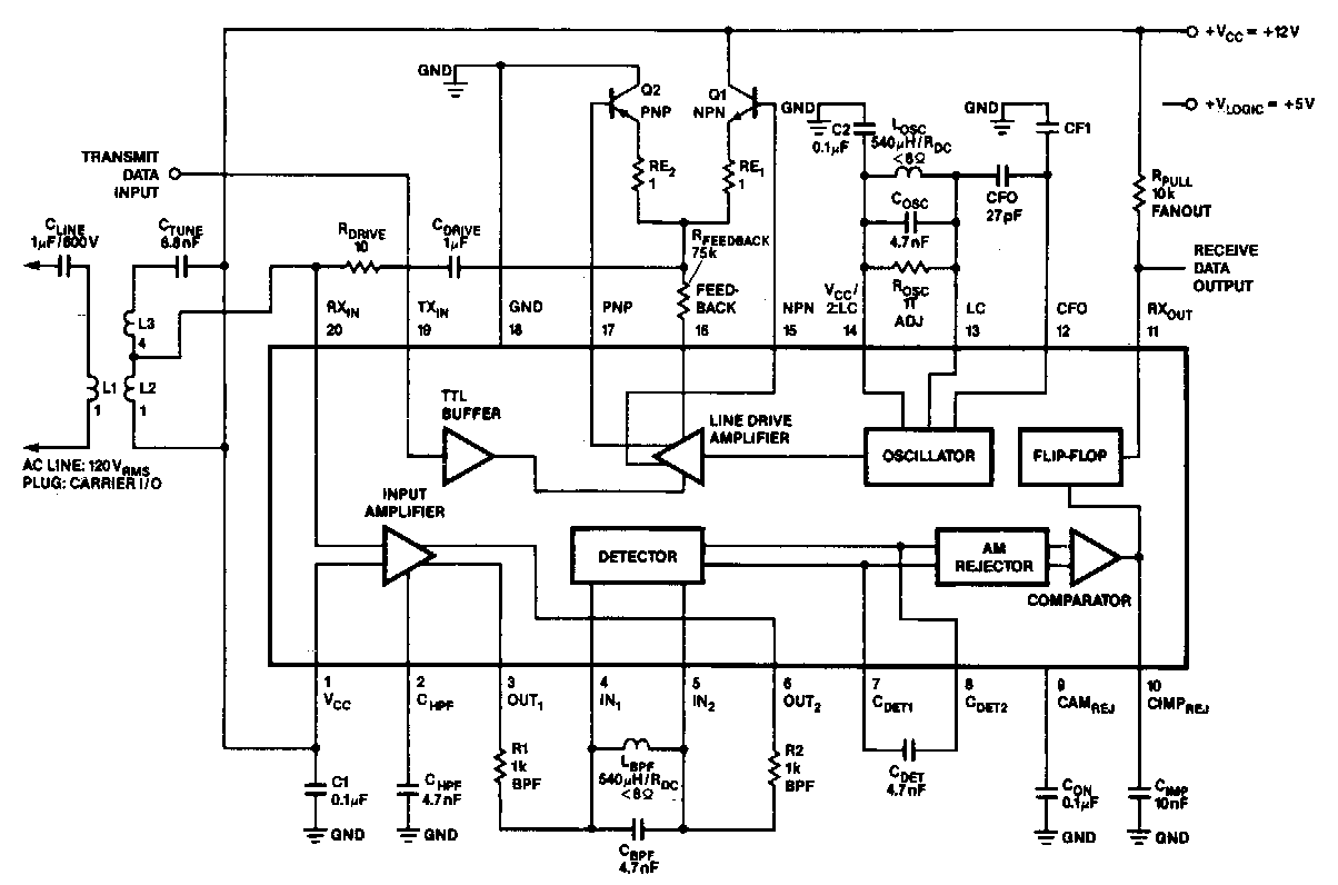
In the 100 kHz application, the coupling network connects to the receiver section located at the bottom of the chip. The external components will be summarized later. The receive data output is pulled up through a resistor (RPuLL) valued...
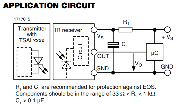
There is an interest in starting an introductory electronics project using an infrared (IR) sensor, but there is some confusion regarding the application circuit provided in the datasheet. The recommended resistor value is significantly lower than the calculated value....
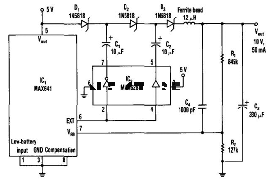
The DC-DC converter replaces a voltage tripler for the external inductor and diode typically associated with the switching regulator, IC1. Inverting and non-inverting amplifiers in the MOSFET driver (IC2) activate a diode-capacitor tripling network (D1 through D3, C1 through...
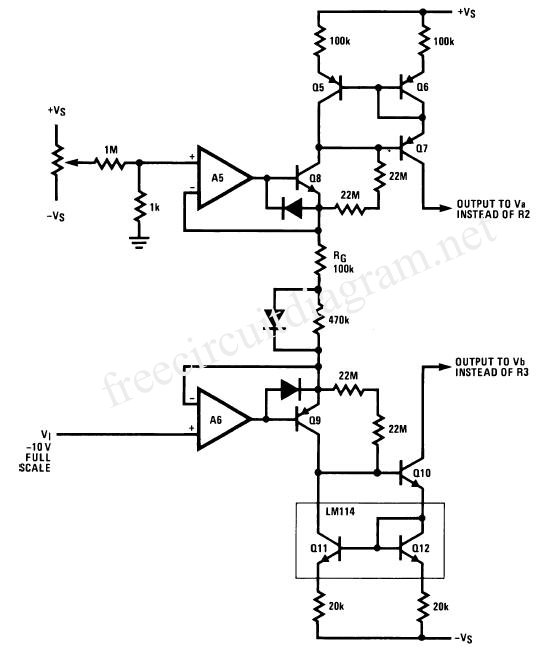
The wide-range current pump for the precision phase-locked loop (PLL) circuit is a semi-precision circuit that provides an output current proportional to -V1, with a variation of approximately 10 to 15%, across a three-decade range. The 22 MΩ resistors...