
Low Frequency Antennas

This active antenna design utilizes a loop configuration that capitalizes on its inductive properties to enhance reception across the shortwave band. The choice of materials, including the Hula-Hoop and copper wire, optimizes the antenna's performance while maintaining a lightweight and easily adjustable structure. The integration of the TL592 differential amplifier is critical, as it not only amplifies the received signal but also addresses impedance matching, which is essential for maximizing signal transfer and minimizing loss. The use of a high-impedance configuration allows for greater sensitivity to incoming signals, further enhancing the antenna's capability to pick up distant broadcasts. The design emphasizes practicality, with components readily available and easy to assemble, making it accessible for hobbyists and enthusiasts looking to improve their radio reception. The balance between performance and cost-effectiveness is achieved through careful selection of components and thoughtful circuit design, allowing for a significant enhancement in radio reception that can be realized in a home workshop setting.Home-made antennas can greatly improve the performance of AM and FM radios, short-wave receivers, and scanners. If you are a talk-radio fan then experiment with the AM band antennas and you will be able to hear shows from all over the country with surprising clarity.
Short-wave receivers are always coping with weak signals and they must have a good antenna to perform adequately. Scanners can pick up local police and two-way radio with the little telescoping antenna provided but with good antennas a scanner becomes an amazing ear on the world nearby. No pre-amp, filter or other receiver refinement offers anywhere near the level of performance improvement t that a well-designed antenna offers.
The results can be quite satisfying, leaving no doubt that the project was well worth the effort. In the past, designs that incorporated an amplifier in the antenna were called "antennafiers" so perhaps this is a "loopifier". The differential amplifier solves matching issues and the varactor tuning gives excellent out-of-band rejection for even cheap receivers.
I think the good common-mode rejection from the differential amplifier eliminates the need for a shield, too. This active antenna for the shortwave band provides surprising performance, even indoors. As the name implies, the main loop is made from a Hula-Hoop with the metallic paint stripped off and a single turn of 14AWG copper wire inserted inside the hoop.
(There isn`t any need to remove the paint; mine was flaking and I didn`t like the looks. Half way through I regretted my decision!) These hoops are basically thin-walled plumbing tubing with a water-tight connector holding the ends together. (Mine was actually filled with water to make a "swish-swish" sound, supposedly. ) The ends of the hoop pass through two holes in a plastic project box and are then joined together. A hole was drilled in the middle of the original black tubing connector to bring out the ends of the insulated house wiring (heavy white wires).
This single turn of wire has about 4 uH inductance. A couple of screws and some epoxy holds the loop in position. The screws were added as an afterthought, cracking the epoxy a bit, because the epoxy doesn`t really adhere to the tubing very well. The solid copper house wire is too stiff to connect directly to the circuit so a couple of lengths of hookup wire were added.
A little piece of tinned copper circuit board material holds the circuitry. The power is supplied by a molded power supply not shown. The circuit avoids matching issues by employing a high impedance differential amplifier (TL592) connected directly across the loop. Even with the Q-killing 4. 7k resistor, the impedance transformation is on the order of 100:1, an impractically high value for a broadband balun of reasonable cost!
Even though the TL592 isn`t the lowest noise amplifier ever designed and the resistor kills some of the signal, this configuration picks up so much signal that the circuit noise contribution is negligible! In fact, the amplifier is operating at a very low gain simply to avoid clipping and most signals push the signal meter well over S-9.
I`ve never heard so many stations! The picture to the right shows the signal strength with the antenna tuned to WWV at 10 MHz with the antenna and receiver sitting on the kitchen table. That beats the nice vertical on my roof. Don`t be misled, however; the antenna doesn`t perform miracles. The atmospheric noise is also amplified so the signal-to-noise does depend on the location of the antenna and other conditions.
Nevertheless, this indoor antenna has consistently outperformed my rooftop whip and when moved outside, it "blows away" the rooftop antenna, in some cases giving a strong signal when the whip gave no discernable signal at all. (Without the Q-killing 4. 7k resistor across the coil, the bandwidth was only 10 kHz at 5 Mhz. That`s a Q of 500! There might be some future projects t 🔗 External reference
Related Circuits
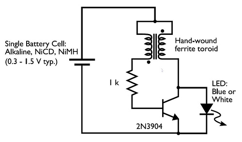
A transformer with two input leads and three output leads was used. An LED was connected to two of the output leads, and when a dead AA battery was connected to the input leads, the LED blinked for a...
This simple circuit uses an incandescent lamp to detect airflow. With the filament exposed to air, a constant current source is used to slightly heat the filament. As it is heated, the resistance increases. As air flows over the...
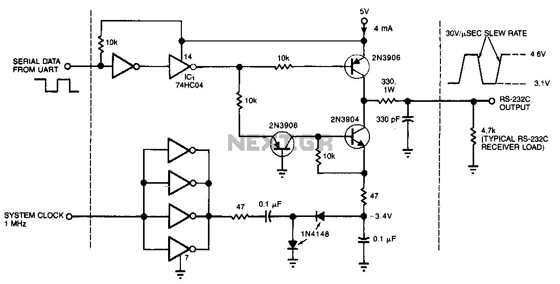
This circuit draws only 4 mA from a 5-V supply while driving a standard RS-232C receiver. The system clock drives a de-de converter that produces -3.4 V. The frequency can range from 0.5 to 8 MHz, but a range...
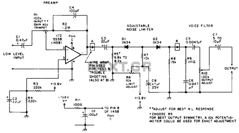
A preamplifier in the audio frequency range amplifies a noisy audio signal to drive a diode clipper. Suitable audio input levels would be in the 10-mV to 1-V range. The audio preamplifier circuit is designed to enhance weak audio signals, typically...
Neon glow lamps can be utilized solely for their voltage/current characteristics rather than for illumination. These lamps are electrically similar to diacs; no current flows through them when the voltage is below a trigger value (approximately 70V for neon...

This circuit represents a waveform generator, which is highly beneficial for electronic experiments and design. It primarily generates sine wave oscillations, but the circuit can be modified to produce triangle or square wave functions. The circuit is based on...