
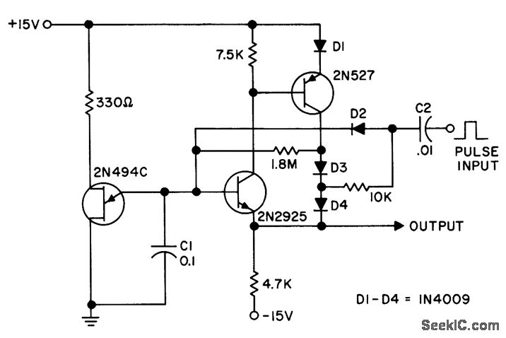
WIDE RANGE STAIRCASE GENERATOR
The circuit operates by utilizing a high input impedance to prevent loading effects that could distort the input signal. This characteristic is essential when interfacing with sensitive signal sources. The low output impedance ensures that the output can drive subsequent stages without significant voltage drop, maintaining signal integrity.
The staircase waveform is created through a charge and discharge cycle facilitated by diode D2 and capacitor C2. During the charging phase, the capacitor accumulates charge, and the diode allows current to flow in one direction, effectively boosting the voltage level at the output. The bootstrapping technique used here helps maintain a consistent output amplitude across each step of the staircase, which is crucial for applications requiring precise voltage levels.
The circuit's design is optimized for a 12-V input pulse, enabling it to generate 10 distinct voltage steps. Each step corresponds to a specific voltage level, allowing for controlled output that can be utilized in various applications, such as analog-to-digital conversion or signal processing. The values of the components used in the circuit are critical for achieving the desired performance and should be selected based on the specific requirements of the application.
In summary, this circuit provides a reliable method for generating a staircase waveform with minimal voltage droop and consistent output levels, making it suitable for various electronic applications requiring precise voltage control.Has high input impedance und low output impedance, to reduce droop in output voltage between pulses. Staircase is generated by pump D2-C2, which is boostrapped on output to maintain equal amplitude on each step. Circuit values shown give 10 steps with 12-V input pulse. -"Transistor Manual, " Seventh Edition, General Electric Co. , 1964, p 345. 🔗 External reference
Related Circuits
Various sawtooth voltage generators utilize the principle of capacitor charging and discharging to produce sawtooth waveforms in both forward and reverse directions. A simple sawtooth voltage generator circuit is straightforward in design; however, it suffers from poor linearity in...
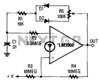
The circuit integrates a charging mechanism through Rl/Dl and the upper half of R5, while discharging occurs via R1/D2 and the lower half of R5. The duty cycle is adjustable within a range of 1:10 to 10:1 through the...
The schematic for this project is significantly more complex than previous designs. There are four primary features in the design: (1) the ability to program the PIC microcontroller on the developed board, (2) control of a servo motor, (3)...
This is a basic 555 square wave oscillator designed to generate a 1 kHz tone for an 8-ohm speaker. In the circuit, the speaker is isolated from the oscillator by an NPN medium power transistor, which supplies more current...
Avoid drilling extra holes and making modifications to the chassis and PCBs, as this will reduce the value of the amplifier and prevent restoration to its original state. It is advisable to take pictures of the amplifier's original condition...
Why an electronic cricket? Many people enjoy the sound of crickets, especially those living in urban areas. This electronic cricket circuit operates in pulses, creating a similar sound. The electronic cricket circuit is designed to replicate the natural sound of...