
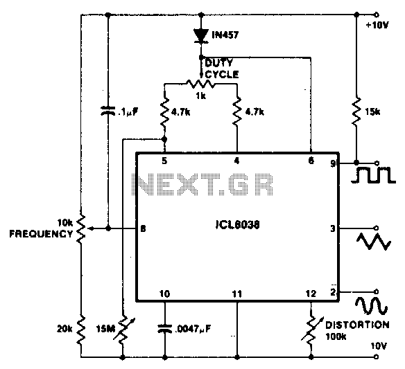
Variable Duty-Cycle Square-Wave Generator

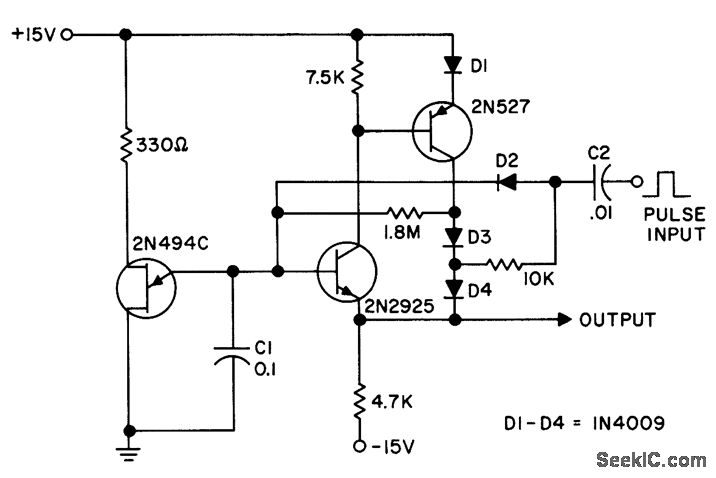
The circuit described involves a charge-discharge cycle managed by a combination of resistors and diodes. The charging phase occurs through the resistor-inductor combination (Rl/Dl) and the upper portion of resistor R5. During this phase, current flows into the capacitor, allowing it to accumulate energy. The discharge phase is facilitated by the resistor-capacitor combination (R1/D2) and the lower half of R5, where the stored energy in the capacitor is released back into the circuit.
The duty cycle, which defines the ratio of the charging time to the total cycle time, can be modified by adjusting R5. This resistor acts as a variable element that influences the time constants associated with both charging and discharging phases. By varying R5, the duty cycle can be set anywhere from 1:10, indicating a longer discharge period compared to the charge period, to 10:1, where the charge period is significantly longer than the discharge period.
This flexibility in the duty cycle allows for tailored applications in timing circuits, pulse width modulation, or other electronic applications where precise control of energy transfer is required. The use of diodes (D1/D2) ensures that current flows in the intended direction during both charging and discharging, preventing backflow and enhancing circuit reliability. The overall design emphasizes efficiency and versatility in managing electrical energy within the specified operational parameters. CI alternately charges via Rl/Dl and the upper half of R5, and discharges via R1/D2 and the lower half of R5. The duty cycle can be varied over the range from 1:10 to 10:1 via R5.
Related Circuits
This circuit generates an accurate and adjustable sine-wave output by removing harmonics from a square wave. This circuit utilizes a harmonic filter to transform a square wave input into a sine wave output. The primary function of this circuit is...
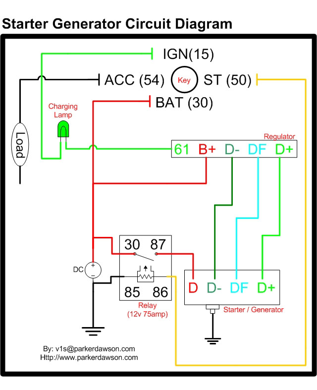
Circuit diagrams for both a Bosch and a Delco-Remy Starter-Generator are available, noting that the circuits differ. Due to a computer crash, the original diagrams and the associated email address were lost. However, in May 2004, both the email...
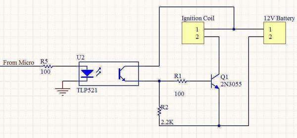
A 12V motorcycle battery and a car ignition coil are utilized in this project. A microcontroller generates pulses to the base of a 2N3055 transistor, which switches the primary of the ignition coil on and off, producing the desired...
The circuit features high input impedance and low output impedance, which minimizes voltage droop between pulses. A staircase waveform is generated by the combination of diode D2 and capacitor C2, which is bootstrapped on the output to ensure equal...
To achieve a 1000:1 sweep range, the voltage across the external resistors Ra and Rb must be reduced to nearly zero. This necessitates that the maximum voltage on control pin 8 surpasses the voltage at the top of Ra...
This is a very useful project for anyone working in electronics. It is a versatile power supply that will solve most of the supply problems arising in the everyday work of any electronics workshop. It covers a wide range...