
555 tone generator 8 ohm speaker
The circuit utilizes the 555 timer in astable mode to create a square wave output at a frequency of 1 kHz. The frequency is primarily determined by the values of two resistors (R1 and R2) and a capacitor (C1) connected to the 555 timer. The output from the 555 timer is fed into the base of the NPN transistor, which acts as a switch to drive the speaker.
The use of the NPN transistor is crucial as it allows the circuit to handle higher currents, making it suitable for driving the 8-ohm speaker without exceeding the current limitations of the 555 timer. The small capacitor connected to the base of the transistor serves to filter out high-frequency noise and smooths the switching transitions, which helps to minimize the inductive kickback voltage produced when the speaker is turned off.
This configuration ensures that the speaker receives a clean and stable 1 kHz tone while protecting the 555 timer from potential damage due to excess current draw. Overall, this simple oscillator circuit is effective for generating audio tones and can be used in various applications such as alarms, sound effects, or educational projects in electronics.This is a basic 555 squarewave oscillator used to produce a 1 Khz tone from an 8 ohm speaker. In the circuit on the left, the speaker is isolated from the oscillator by the NPN medium power transistor which also provides more current than can be obtained directly from the 555 (limit = 200 mA). A small capacitor is used at the transistor base to slow the switching times which reduces the inductive voltage produced by the speaker..
🔗 External reference
Related Circuits
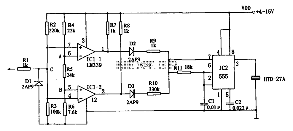
The acoustic logic level probe circuit consists of a voltage comparator, multivibrator, piezoelectric ceramics (HTD), and other components. The configuration of the audio circuit determines the frequency of the sound level to assess the logic levels of TTL or...
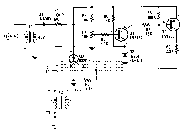
A step-down transformer T1 reduces the incoming line voltage to approximately 48 Vac, which is then rectified by diode D1. The resulting direct current charges capacitor C1 through a current-limiting resistor R1 to a voltage level set by R4....
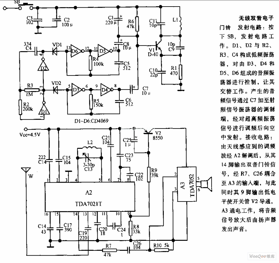
The transmitter circuit is activated by pressing the SB button. Components D1, D2, R2, R3, and C4 form a low-frequency oscillator that controls an audio oscillator made up of D3, D4, D5, and D6, allowing them to operate alternately....
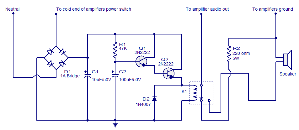
When the amplifier is powered on, the speaker experiences a sudden high voltage, resulting in a loud thud sound. This phenomenon is detrimental to the speaker and significantly shortens its lifespan. The circuit illustrated here connects the speaker to...
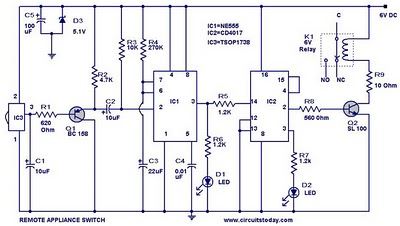
555 Timer TV Remote Controlled Home Appliance Circuit Diagram. Features: 555 timer IC to avoid fast switching. You can only switch the circuit. The 555 timer integrated circuit (IC) is a versatile component widely used in various electronic applications, including...
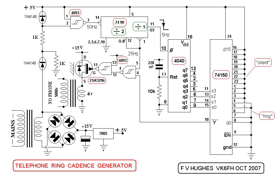
This design aims to restore the classic style of telephones that utilized a pair of gongs to signal an incoming call, evoking a sense of nostalgia with the familiar sound of ringing bells. Presented here is a "Telephone Ring...