
Wideband Active Small Magnetic Loop Antenna
The construction of the loop should adhere to the principle that maximizes the ratio of loop area to loop inductance. This leads to the conclusion that a circular shape with one turn is optimal. A practical diameter of approximately 1 meter with the thickest possible conductor is recommended. The material can be copper or aluminum, as the loop Q-factor is not critical; what matters is achieving low loop inductance. A 1-meter diameter loop made from aluminum wire with a diameter of 3.4 mm results in an inductance of around 4 µH. Additionally, a 0.9-meter diameter loop constructed from double foil FR-4 PCB material (1.5 mm thickness and 20 mm width) can reduce the loop inductance to 3 µH. Optimal performance can be achieved with "parallel" and "crossed parallel" loops (CP loop). For urban environments with elevated noise levels, smaller loops may be more suitable. This antenna is designed for outdoor use, with the amplifier housed in a small, IP55-rated plastic enclosure. Such enclosures are readily available on the market, and any similar variant can be utilized.
The connection between the antenna and the receiver (RX) employs a shielded LAN cable of the FTP type, featuring four twisted pairs. Separate pairs are designated for signal and power transmission. Standard RJ45 connectors are employed, which are cost-effective and reliable; however, the RJ connector should be placed inside the enclosure as it is not waterproof. Shielding of the enclosure is unnecessary, as it is assumed the antenna will be positioned several meters away from electrical equipment, minimizing direct near-field interference with the amplifier board. The FTP shield must be connected to the RX ground (chassis), while the far end (antenna side) should be left floating. If an independent DC power supply is used, the power supply ground should also be floating. It is advised to avoid switching power supplies, as they may introduce challenging noise issues.There are now extremely wideband software defined radios (SDR) where the wideband antenna is a natural choice. Wideband small magnetic loops (WSM loop) are used already 3-4 decades and I was curious to see what can be reached with them and to evaluate their usefulness as a wideband SDR input.
The WSM loop should work in short circuit mode in order to reach flat frequency response in wideband frequency range. The antenna should be used with an amplifier since the loop current is very small. This amplifier must be with very low input impedance. A circuit diagram of active WSM loop antenna is shown on Fig.1. The antenna specification is given for 1m diameter circular loop with aluminum conductor with diameter 3.4 mm.
Specification Diameter: 1 m, 1 turn Material: aluminum conductor with 3.4 mm diameter Loop inductance: 4 uH Antenna Factor Ka: 6 dB meters-1 @ 10 MHz (computed from the spice model) (1 uV/m input signal will give 0.5 uV output voltage) Flatness: Within 3 dBmeters-1 0.5 – 30 MHz; (computed from the spice model) Noise floor: >= 0.7 uV/m (computed from the spice model) Power supply: Remote, 13.5 V >150 mA Dynamic range: TBS; 1 dB Compression point >= 130 dBuV/m ( 5.6 V/m p-p output voltage, from the spice model)
The construction of the loop should be considered with the following rule: the ratio of loop area to loop inductance should be maximized (see the Appendix) . That automatically means that circular shape with 1 turn is the best choice. The practical diameter is around 1 m with the conductor as fat as possible. The material might be copper or aluminum – actually the loop Q-factor is not important. The important factor is the low loop inductance. 1m diam. loop made from aluminum wire 3.4 mm gives inductance around 4 uH. I have used also 0.9 m diam. loop made from double foil FR-4 PCB material (Fig.3) with 1.5mm thickness and 20 mm width which reduces the loop inductance to 3 uH.
The best results can be obtained with “parallel” and “crossed parallel ” loops (CP loop, see Fig. 5 , 13,14 , Appendix I,II). For urban locations where the noise level is much higher smaller loops can be used. This antenna will be used outdoors and the amplifier is placed in a small, IP55 secured, plastic box (Fig.2).
These boxes are widely available on the market - any similar one can be used. The connecting cable between the antenna and receiver (RX) is shielded LAN cable FTP type with 4 twisted pairs. The signal and power use separate pairs. RJ45 standard connectors are used. These connectors are very cheap and reliable but the RJ connector should to be placed inside the box since it is not waterproof.
There is no need for the box to be shielded – it is supposed that the antenna will be mounted at least several meters away from electrical equipment and direct near field influence to amplifier board will be reduced. The FTP shield must be connected to RX ground (chassis), but at the far (antenna) end should be left floating.
The power supply (PS) ground also is floating if independent DC supply is used. Do not use switching PS - it will be very difficult to remove its noise.
Related Circuits
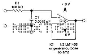
This simple filter utilizes an RC section as the filter element, incorporating a voltage follower to manage other frequencies. The -3 dB point is calculated as 1/(6.28 * RXCV), resulting in a response that drops 6 dB per octave...
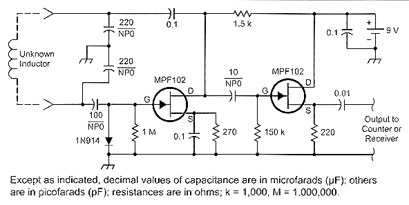
How can small inductances be measured with a precision of at least two, and possibly three, significant digits? A review of the literature yielded limited results. One noteworthy circuit was detailed in the 2001 ARRL Handbook on page 26.22....
The antenna tuning circuit can accommodate 1/2 wave length antennas or higher, for input resistances of 50 Ohms which make it suitable for CB (Citizen Band) transceivers. C1 is for fine tuning and C2 is just for tuning. Turning...
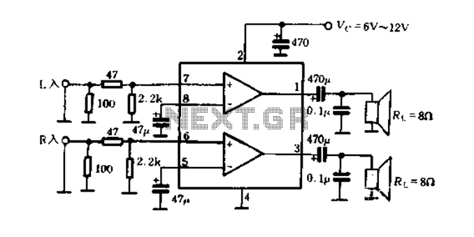
The elements and internal function diagram are depicted in Figure 9-50. Capacitors C1, C2, and C3 represent feedback capacitance, which changes with low-frequency variations within a specific cutoff frequency range. Capacitor C5 serves as the output coupling capacitor, typically...
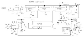
This 860 MHz Phase Locked Loop (PLL) oscillator circuit is designed for a 1200 MHz transverter's local oscillator with 435 MHz rigs. The oscillator utilizes Toshiba PLL synthesizer integrated circuits (ICs). The TC9122P serves as a preset counter for...
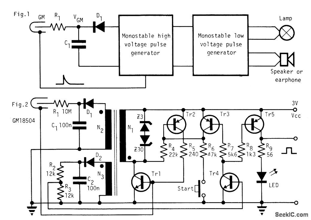
In the absence of radiation, no current is drawn. At normal background radiation levels, the power consumption is extremely low. The instrument may be left on for several months without changing batteries. In this way, the detector is always...