
Antenna tunning circuit for 27MHz CB band
The antenna tuning circuit described is designed to optimize the performance of 1/2 wave length antennas, specifically for use with Citizen Band (CB) transceivers that typically operate at an input resistance of 50 Ohms. The circuit incorporates three capacitors: C1, which is utilized for fine tuning; C2, which serves as the primary tuning capacitor; and C3, which is adjusted in conjunction with C2 to achieve a standing wave ratio (SWR) of 1:1, indicating a perfect match between the antenna and the transceiver.
The inductor, labeled L, consists of 11 turns of insulated copper wire with a diameter of 1mm, forming a coil that plays a crucial role in the tuning process by providing the necessary inductance to match the impedance of the antenna system. The configuration of the coil and the capacitors allows for the adjustment of the resonant frequency of the circuit, enabling it to accommodate varying lengths of antennas beyond the standard 1/2 wave length.
When using a 1/2 wave length antenna, which measures approximately 5.5 meters, it is essential to set C3 to its maximum capacitance to ensure optimal performance. The circuit can interface with the receiver via either an SO-239 connector, which is a UHF type commonly used in RF applications, or through BNC connectors, providing versatility in connection options. To minimize signal loss and maintain signal integrity, it is recommended to keep the cable length between the transceiver and the tuning circuit as short as possible. This design ensures efficient transmission and reception of signals, making it suitable for CB communication applications.The antenna tunning circuit can accommodate 1/2 wave length antennas or higher, for input resistances of 50 Ohms which make it suitable for CB (Citizen Band) transceivers. C1 is for fine tunning and C2 is just for tunning. Turning C3 with the help of C2 you can set the SWR to 1:1. The Coil L is made of 11 turns of insulated copper wire with diameter of 1mm. If you use 1/2 wave length antenna (5.5m) then C3 has to be set to highest capacitance. The connection with the receiver can be done using the SO-239 connector (UHF) or with BNC's. Keep the distance of the cable between the transceiver and the tunning cir 🔗 External reference
Related Circuits
This circuit can be directly connected to CD players, tuners, and tape recorders. It requires the addition of a 10K logarithmic potentiometer (dual gang for stereo) and a switch to accommodate various sources. Proper grounding is crucial to eliminate...
Many RC oscillators utilize advanced circuits within the phase shift unit. These circuits employ voltage feedback amplifiers, whose gain decreases significantly at high frequencies and ceases when high frequency is not attained. The variation in the phase characteristics of...

Basic features include an internal 512k-bit EEPROM, allowing for continuous recording and playback at any time, with long-term retention of voice data after power loss. The voice recording time is 20 seconds, and it supports segmented recording and playback....
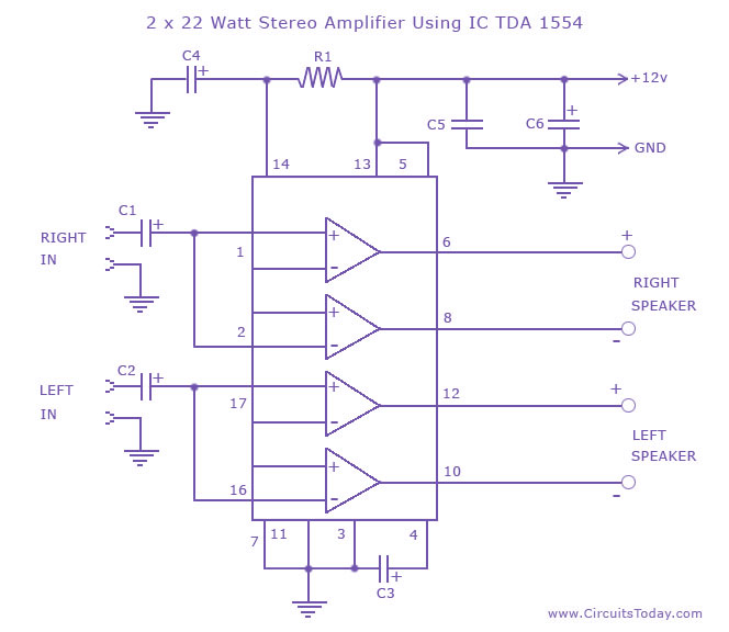
A high-quality stereo amplifier circuit of 44 Watts (22 Watts per channel) using the TDA 1554 IC. This is a powerful audio amplifier circuit for 2 channels. The described stereo amplifier circuit utilizes the TDA 1554 integrated circuit (IC), which...
A use has been found for a collection of DIP-style RF relays acquired from a discount electronics shop. These relays are completely sealed and RF shielded, featuring low contact capacitance, making them suitable for VHF frequencies. They operate at...
This circuit diagram for a 12V inverter is simple to construct and utilizes inexpensive components that many electronics hobbyists may already possess. While it is feasible to create a more powerful circuit, the complexity arises from managing the significant...
Warning: include(partials/cookie-banner.php): Failed to open stream: Permission denied in /var/www/html/nextgr/view-circuit.php on line 713
Warning: include(): Failed opening 'partials/cookie-banner.php' for inclusion (include_path='.:/usr/share/php') in /var/www/html/nextgr/view-circuit.php on line 713