
Wideband noise generator
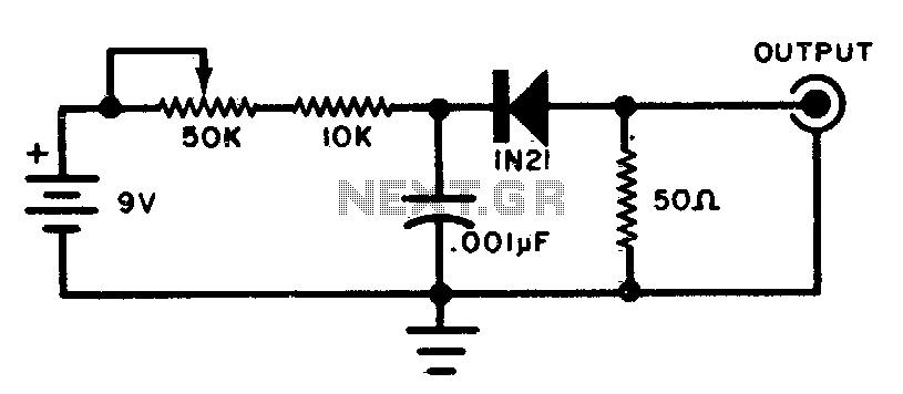
The circuit primarily consists of a reverse-biased diode, which serves as the core component for generating RF noise. When reverse-biased, the diode operates in a breakdown region, producing noise across a wide frequency range. This characteristic is essential for applications requiring random noise signals, such as in the alignment of radio receivers.
The low-impedance output is crucial for interfacing with other circuit components, ensuring that the generated noise can be effectively coupled to the receiver circuitry without significant signal loss. This configuration allows for better matching with the input stages of receivers, which often have low input impedance.
In practical applications, the circuit can be integrated into a test setup where it can provide the necessary noise signal for tuning and optimizing the performance of various RF receivers. The wideband nature of the noise produced ensures that it can cover the entire frequency spectrum of interest, making it suitable for a range of RF applications, from AM to FM and beyond.
Additional components may be included in the circuit design, such as resistors and capacitors, to filter and shape the noise signal as required for specific applications. Proper PCB layout and component selection will also enhance performance, ensuring minimal interference and optimal signal integrity during operation.This circuit will produce wideband rf noise. It uses a reverse-biased diode and has a low-impedance output Can be used to align receivers for optimum performance. 🔗 External reference
Related Circuits
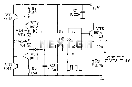
The circuit depicted involves transistors VT1, VT2, and resistor R1, which form a constant current source for charging capacitor C2 in a linear manner. Transistors VT3, VT4, and resistor R2 create a constant current source for discharging capacitor C2,...
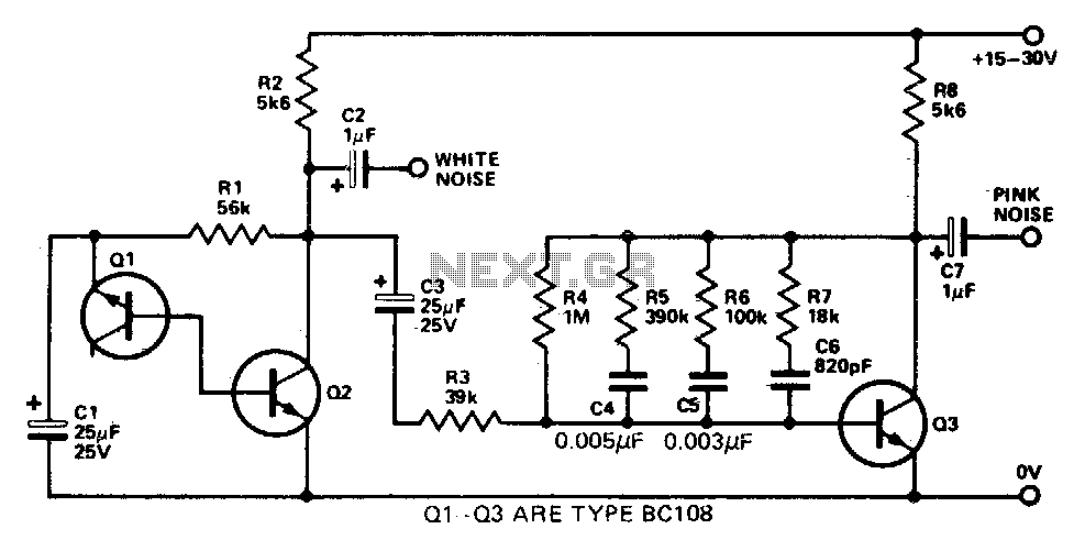
This simple circuit generates both white and pink noise. Transistor Q1 functions as a zener diode, with the base-emitter junction being reverse-biased to achieve zener breakdown at approximately 7 to 8 volts. The zener noise current from Q1 flows...

A simple yet effective circuit to generate a POTS-compatible ringing voltage can be constructed using National Semiconductor's LM4871 audio amplifier IC along with a dozen passive components. This circuit produces a sine-wave output of 1 W at approximately 70...

The circuit illustrated in Figure 1 generates a precise variable-frequency sine wave intended for use as a general-purpose reference signal. It incorporates an 8th-order elliptic switched-capacitor low-pass filter (IC3), which is clocked by a 100 kHz square wave produced...
This type of design can generate a very high amperage current for a fraction of a second, which can be utilized for various applications if properly harnessed. The switching device could be a rotating spark gap, as utilized by...
This ring generator will ring a telephone once every 10 seconds. The interval between rings can be lengthened or shortened by varying the value of the 1 Meg resistor. The 70 volt/ 30 Hz ring voltage is produced from...
Warning: include(partials/cookie-banner.php): Failed to open stream: Permission denied in /var/www/html/nextgr/view-circuit.php on line 713
Warning: include(): Failed opening 'partials/cookie-banner.php' for inclusion (include_path='.:/usr/share/php') in /var/www/html/nextgr/view-circuit.php on line 713