
Single-Dual digital LED dice circuit
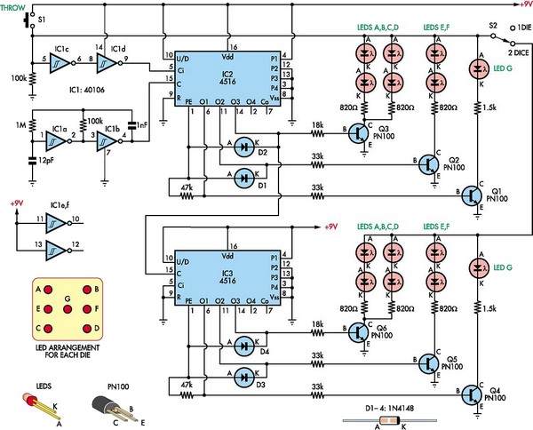
The circuit design employs two 4516 ICs, which are dual 4-bit binary counters. These counters will effectively simulate the random output of dice rolls by generating binary numbers that correspond to the values of the dice. Each IC can count from 0 to 15, but for the purpose of simulating dice, the outputs will be limited to the range of 1 to 6, which can be achieved through additional logic circuitry.
The switching mechanism allows the user to select between one or two dice rolls. This can be implemented using a single-pole double-throw (SPDT) switch that alters the circuit configuration to enable either one or both counters. When the switch is set to one die, only one of the 4516 ICs will be active, while the second IC remains inactive. Conversely, when the switch is set to two dice, both ICs will be engaged, and their outputs will be displayed simultaneously.
Powering the circuit with a 9-volt battery provides adequate voltage for the 4516 ICs, ensuring reliable operation. The circuit should include appropriate decoupling capacitors near the power pins of the ICs to minimize noise and improve stability.
The output of the counters will be displayed using LEDs, which will visually represent the results of the dice rolls. Each die's output will be connected to a set of LEDs arranged in a manner that corresponds to the numbers 1 through 6. The design should ensure that only one LED lights up at a time for each die, representing the rolled value. This can be accomplished using a combination of resistors and transistors to control the current flowing to each LED based on the binary output from the ICs.
The construction of the circuit within a small enclosure will not only enhance portability but also provide protection to the components. Careful attention should be paid to the layout to ensure that all connections are secure and that the LEDs are positioned according to the schematic diagram for optimal visibility.By using two 4516 ICs, this circuit will simulate two dices playing game. There is a switch to choose if one or two dices will be run at each throw pressing. A 9 volt battery willl be ok. Make a nice small box and place the LEDS acorcding to the diagram shown. 🔗 External reference
Related Circuits
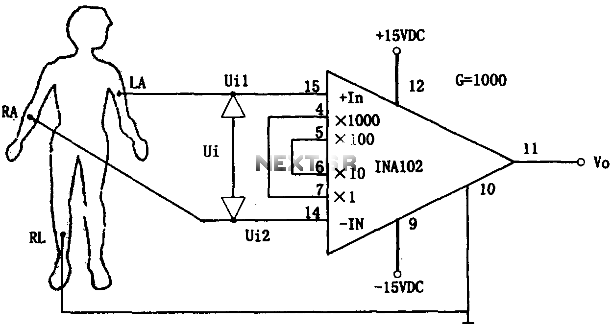
This document outlines a preamplifier circuit designed for measuring human biological signals, such as ECG and EEG. These biological signals are typically weak and require high amplification circuits. The circuit utilizes a low-power integrated operational amplifier, INA102. The INA102...

The circuit utilizes a 555 timer integrated circuit along with a transistor (VT) and several external components to create a multivibrator circuit. The charge and discharge time constants, Ti and T2, are defined, where Ti is approximately 0.7 times...
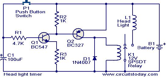
This circuit is a compact timer that keeps the headlights of a car on for approximately 1.5 minutes before turning them off. Incorporating this circuit into a vehicle allows access to dark areas without the need to return and...

This circuit utilizes a Power Battery Terminal (PBT) to facilitate simple relay output and auxiliary power connections. An LED on each channel serves to indicate the status of the relay. Berg pins are provided for connecting power and trigger...
Video-DVM is a very cheap DVM that shows how an output as complex as a videocomposite signal can be generated entirely in software: two I/O pins and three resistors are all the hardware required. Connected to any TV set...
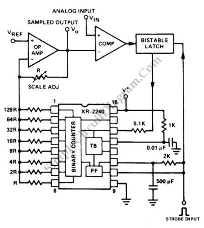
To hold an analog signal for an extended period, a digital sample and hold circuit is an effective solution. This circuit utilizes the Exar XR-2240 programmable timer/counter as its main component. The Exar XR-2240 is activated when a strobe...
Warning: include(partials/cookie-banner.php): Failed to open stream: Permission denied in /var/www/html/nextgr/view-circuit.php on line 713
Warning: include(): Failed opening 'partials/cookie-banner.php' for inclusion (include_path='.:/usr/share/php') in /var/www/html/nextgr/view-circuit.php on line 713