
wien bridge oscillator circuit

The Wien bridge oscillator is a type of electronic oscillator that generates sine waves. The essential components of this circuit include resistors, capacitors, and an operational amplifier. The configuration typically consists of a bridge circuit formed by two resistors and two capacitors, which are arranged in a way that allows for both positive and negative feedback.
The circuit operates by balancing the gain of the op-amp with the attenuation of the bridge circuit. When the op-amp is powered, it amplifies the voltage across the feedback network until the gain is equal to the attenuation, allowing the circuit to oscillate. The frequency of oscillation is primarily determined by the values of the resistors and capacitors used in the circuit, specifically by the formula:
\[ f = \frac{1}{2\pi R \sqrt{C_1 C_2}} \]
where \( R \) is the resistance used in the bridge, and \( C_1 \) and \( C_2 \) are the capacitances in the feedback loop.
In practical applications, the Wien bridge oscillator is often implemented with a rail-to-rail op-amp to maximize the output voltage swing and ensure that the waveform remains within the power supply limits. This is particularly advantageous in battery-powered devices or systems requiring high dynamic range.
The output of the oscillator can be further utilized in various applications, such as signal processing, audio synthesis, and testing equipment, where a stable sine wave is necessary. The design can also be modified to include additional features such as amplitude stabilization or frequency tuning, which can enhance the versatility and performance of the oscillator in real-world applications.This is a circuit that is known as wien bridge oscillator circuit. The circuit has positive and negative feedback loop. This circuit is work with control by op amp. This is the figure of the circuit. The circuit oscillates at a frequency determined by the RC time constant at frequency and produces a sinusoidal waveform at the output voltage Vout. In many cases this circuit is used as sine wave generator which is using rail to rail op amp. [Schematic`s diagram source: Advanced Linear Devices, Inc] 🔗 External reference
Related Circuits
SPI Integrated Circuit Bus, IC Buses, an IC, Chip-to-Chip Bus Serial Peripheral Interface, Integrated Circuit Bus types, and IC Bus Electrical Interface Descriptions. Peripheral Interface (SPI) circuit is a. The Serial Peripheral Interface (SPI) is a synchronous serial communication...
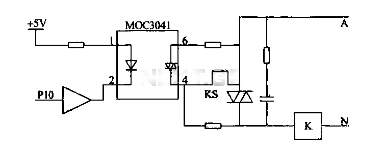
Device for an intermediate relay. The circuit utilizes a Triac AC contactor interface, employing the MOC3041 Triac output optical coupler to trigger the Triac. When Pl0 is low, the Triac will be activated, energizing the AC contactor coil. The described...
An increasing number of appliances draw a very small current from the power supply. If designing a mains-powered device, one can generally choose between a linear and a switch-mode power supply. However, when the appliance's total power consumption is...
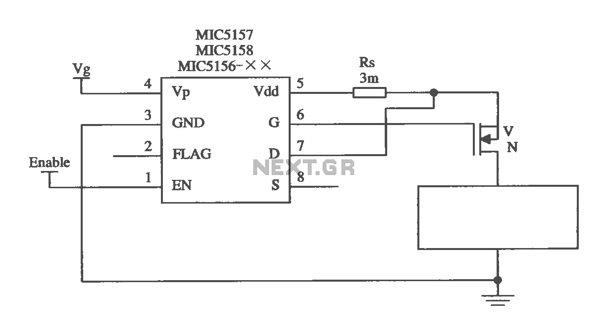
The MIC5156 is a device that incorporates a current limiting function, allowing it to handle high output currents. It can operate with or without a switching regulator circuit. The S terminal is left vacant, and a 16V Zener diode...
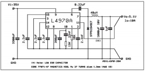
A small-sized and easy-to-build 5V 10A power supply circuit is being sought. This circuit utilizes the L4970A integrated circuit as a 10A switching regulator. It is essential that the power supply input can handle a current of 10A to...
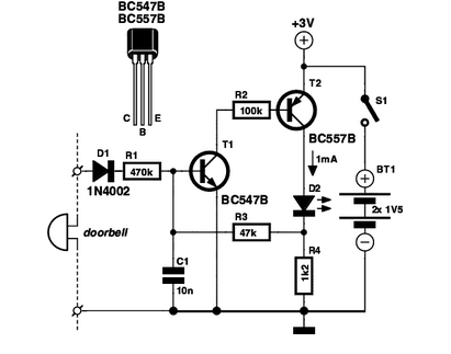
If you are expecting an important visitor but need to step out for a moment, an electronic doorbell memory can be useful to check who rang the bell. An electronic doorbell memory system is designed to capture and store the...