
Wien Bridge Oscillator Design
The Wien Bridge Oscillator is a fundamental circuit used for generating sine waves, characterized by its simplicity and effectiveness. It operates based on the principles of feedback and phase shift, utilizing resistors and capacitors to create the necessary conditions for sustained oscillation. The circuit is typically implemented with an operational amplifier (op-amp), which serves as the active component providing the necessary gain.
In the circuit, the combination of resistors and capacitors forms two networks: a series RC network and a parallel RC network. The series network consists of R1 and C1, while the parallel network comprises R2 and C2. These components are strategically chosen to ensure that the phase shift introduced by the Wien bridge network is precisely 0 degrees at the desired frequency of oscillation. This is critical because any deviation from this condition would prevent the circuit from achieving stable oscillations.
The gain of the circuit is crucial for overcoming inherent losses that occur due to the non-ideal characteristics of real components, such as resistive heating and amplifier limitations. The requirement for a gain of 3 arises from the need to compensate for these losses while ensuring that the feedback signal remains in phase with the input signal. The feedback resistor configuration, where R3 is set to be double the value of R4, establishes this gain.
Moreover, the design incorporates a mechanism to adjust the gain dynamically. A variable resistor or a transistor can be employed in place of R4, allowing the circuit to adapt as the output changes. This feature is essential for initiating oscillation, as a higher gain is needed to start the process. Once the oscillation is established, the gain must stabilize at 3 to maintain consistent output without distortion.
The Wien Bridge Oscillator is widely used in various applications, including audio signal generation, function generators, and other electronic devices requiring precise sine wave outputs. Its straightforward design and effective operation make it a popular choice among engineers and designers. Understanding the intricacies of this oscillator can lead to improved designs and applications in electronic systems.One of the simplest sinewave oscillators is the Wien Bridge Oscillator. Any circuit requires 2 conditions to oscillate. Tracing the path from the input, round the feedback network, back to the input there must be an overall phase shift of 0 degrees at one particular frequency. In other words, any signal travelling around this loop, must be in phas e with the original signal as it arrives back at the input and thus add to the input signal. As the signal travels around the loop, there will be a loss in the system (heat dissipation in the components, losses in the amplifier etc). Therefore there must be some form of gain in the loop, such that the signal arriving back at the input (having travelled around the loop) is larger than the original signal.
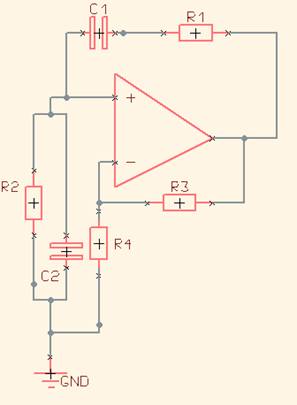
If these 2 conditions are met, the oscillations will be sustained. FIG 1 shows a typical Wien bridge oscillator. The circuit relies on the series RC network (made up of R1 and C1) and the parallel RC network (made up of R2 and C2) causing a phase shift of 0 degrees at one particular frequency at the non inverting input. Thus from what we have said, taking the signal at the + input, through the op amp, through R1 and C1 and back to the + input causes a phase shift of 0 degrees at one particular frequency.
The following involves some equations that look a bit hair raising, but if you compare FIG1 with a normal non inverting op amp circuit and have a rough grasp of how capacitors vary their characteristics with frequency, you should be able to follow them. An easy way of analysing this circuit is to consider the gain and phase shift caused by the Wien bridge network (the series and parallel RC components) and ignore the other components in the circuit, as shown in FIG 2 The parallel combination of 2 resistors is equal to the product divided by the sum of the resistors.
The same is true with a parallel combination of a resistor and a capacitor. As the j terms cancel out, there is no phase shift i. e. there is no j term on the top or the bottom of the above number. We therefore have zero phase shift from output to input, so we have achieved half of our criteria for oscillation We know that for oscillation to occur, the gain of the loop has to be 1 so we need to have a gain of 3 to overcome the loss` of 1/3 going from output to input. With a simple op amp circuit, if an input is applied to the non inverting terminal (+) then the feedback resistor (R3 in FIG 1) has to be twice R4 to get a gain of 3 since The same is true with the oscillator circuit.
To get a gain of 3, R3 has to be exactly 2x R4. This has to be maintained throughout the entire operation of the circuit so a certain amount of variability has to be built into the gain components. We also need a gain of >3 to start the circuit up, then the gain must limit to 3 to maintain correct operation.
To achieve this, a transistor is normally placed in the position of R4 that changes its resistance according to output voltage. As the output grows its resistance increases to reduce the overall gain. 🔗 External reference
Related Circuits
A variable audio oscillator operates within a frequency range of 20 hertz to 20 kilohertz. The circuit utilizes an Intersil 8038 waveform generator, which is designed in a 14-pin dual in-line package (DIP). The variable audio oscillator circuit is designed...
A NE555 integrated circuit (IC) is utilized for the design of a variable low-frequency oscillator, and a schematic is provided. The NE555 timer IC is a versatile and widely used device in various electronic applications, particularly in generating precise timing...
Any vacuum-tube oscillator configuration has an equivalent transistor circuit. For example, consider the vacuum-tube oscillator, illustrated in Fig. 6-1 (A), which represents one form of Hartley oscillator. Positive feedback is accomplished by arranging the resonant tank E to be...
The Colpitts oscillator has been redrawn for clarity. The inductor (L) is approximately 1.5 µH with 19 turns wound on a T50-6 core (yellow). The capacitor (C6) value has been determined experimentally, with a combination of 69 pF (using...

This lie detector circuit provides two readings: one for difficult questions and another for the subject's general emotional state. Two flexible, uninsulated wires wrapped around the fingers or wrist can serve as electrodes. Each change in resistance, and consequently...
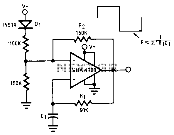
This self-starting fixed-frequency oscillator circuit provides excellent frequency stability. R1 and C1 form the frequency-determining network, while R2 delivers the regenerative feedback. Diode D1 improves stability by compensating for the difference between VaH and VsurrLY. In applications where a...
Warning: include(partials/cookie-banner.php): Failed to open stream: Permission denied in /var/www/html/nextgr/view-circuit.php on line 713
Warning: include(): Failed opening 'partials/cookie-banner.php' for inclusion (include_path='.:/usr/share/php') in /var/www/html/nextgr/view-circuit.php on line 713