
Transistor Hartley Oscillator

The vacuum-tube oscillator configuration serves as a foundational model for understanding its transistor equivalent, particularly in the context of the Hartley oscillator. In the vacuum-tube implementation, positive feedback is achieved by integrating a resonant tank circuit with both the input grid and output plate circuits. The corresponding transistor circuit, depicted with a grounded emitter configuration, similarly employs a resonant tank that interfaces with the input base and output collector circuits to facilitate positive feedback.
When the emitter lead is disconnected from ground and repositioned at the base of the tank circuit, the fundamental electrical behavior of the oscillator remains intact. A further transformation into a grounded-base configuration illustrates the versatility of the circuit design. In this configuration, the grid bias in the vacuum-tube oscillator is managed by a grid leak resistor, while the transistor circuit achieves self-biasing through a resistor connected to the base.
All configurations utilize an R-F choke to decouple the battery supply, ensuring stable operation. A critical distinction between the vacuum-tube and transistor oscillators lies in the impact of emitter resistance on the tank coil. This resistance manifests as an equivalent shunting resistance, which, along with the collector resistance, influences the overall behavior of the resonant circuit. Oscillation initiates when the shunt resistance is effectively counterbalanced by the emitter's negative resistance, thereby establishing a condition for sustained oscillation.
The optimal tap point of the coil is determined by the feedback turns ratio and the emitter-to-collector current gain, with the efficiency of oscillation peaking as the gain approaches unity. The minimum parallel resistance of the tank circuit is also derived from these parameters, indicating the importance of precise calculations in circuit design, particularly regarding the inductance of the tank coil and its resonant frequency.
To mitigate the drawbacks associated with coil tapping, alternative feedback paths can be employed, as illustrated in subsequent figures. These configurations utilize a feedback resistor, which may be a choke, to form an AC voltage divider with the resonant circuit's impedance. By adjusting the feedback resistor's value, the necessary feedback for stable oscillation can be achieved, underscoring the adaptability and precision required in oscillator circuit design.Any vacuum-tube oscillator configuration has an equivalent transistor circuit. For example, consider the vacuum-tube oscillator, illustrated in Fig. 6-1 (A), which represents one form of Hartley oscillator. Positive feedback is accomplished by arranging the resonant tank E to be common to both the input grid and output plate circuits. The equivalent transistor circuit using a grounded emitter connection is illustrated in Fig. 6-1 (B). Again, positive feedback is provided by placing the resonant tank so that it is common to both the input base and output collector circuits. If ground is removed from the emitter lead, and placed at the bottom of the tank circuit, the electrical operation of the oscillator is unchanged.
Notice that when this circuit is rearranged as illustrated in Fig. 6-1 (C), it is now in the grounded-base connection. While the grid bias of the vacuum-tube oscillator in Fig. 6-1 (A) is regulated by the grid leak resistor RG, the equivalent transistor base in Fig. 6-1 (C) is self-biased through resistor RB. In all three circuits, the battery supply is decoupled by an R-F choke. The major difference between the operation of the vacuum-tube Hartley oscillator and that employing a transistor lies in the loading effect of the emitter resistance on the tank coil. This resistance is reflected into the tank circuit and acts as an equivalent shunting resistance. The tank is also shunted by the collector resistance, and the equivalent shunt resistance of the resonant circuit becomes.
Oscillation starts when the equivalent shunt resistance of the tank is counterbalanced by the reflected negative-resistance of the emitter. The optimum tap point of the coil (as determined both mathematically and, where T is the ratio of the feedback turns included in the emitter circuit to the total number of tank coil turns, and ± is the emitter-to-collector current gain.
Notice that when ± approaches unity, the transistor oscillates at highest efficiency with a center-tapped tank coil. Under this condition the minimum allowable parallel resistance of the tank circuit is, where ‰ = 27G£fo, re is the transistor resistance, fo is the resonant frequency, arid L is the inductance of the tank coil.
The operating resonant frequency is always lower than the isolated resonant tank frequency, because of the change in effective value of inductance caused by the coil tap. The disadvantages of tapping the coil can be avoided by using a direct feedback path from the resonant circuit to the input terminal.
Figures 6-2 (A) and 6-2 (B) illustrate two such possible arrangements. In both examples, the feedback resistor RP (a choke may be used) and the effective impedance of the resonant circuit form an a-c voltage divider. The value of RF can be adjusted to obtain the required amount of feedback for sustained oscillation. 🔗 External reference
Related Circuits
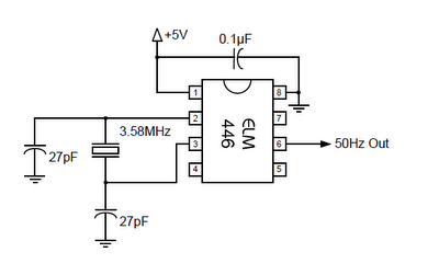
The ELM446 is an 8-pin digital divider integrated circuit that generates both 50Hz and 1Hz outputs from a common 3.58MHz NTSC colorburst crystal. The designer needs to supply only the crystal and two suitable loading capacitors, along with a...
The RF engineer sometimes needs an instrument that can reliably and quickly test a low-frequency quartz crystal unit. Finding such equipment can be challenging, and engineers often refer to electronic circuit handbooks for schematics that can perform this task....
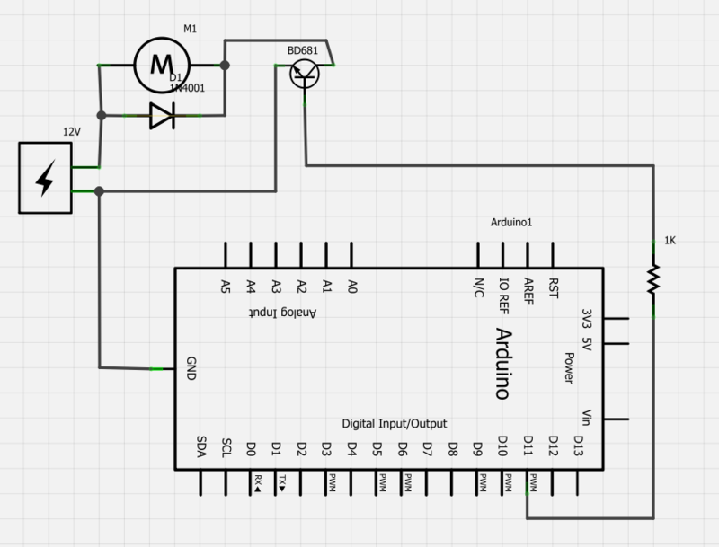
Power a 12V fan using a Darlington transistor to control the speed from an Arduino. When wired as described, nothing happens even though a PWM signal is being sent. It is suggested to edit the question and ensure the...
The circuit below requires a double pole, double throw relay in conjunction with a single transistor to allow toggling the relay with a momentary push button. One set of relay contacts is used to control the load, while the...
It had been a little over a decade since the invention of the transistor when this article appeared in the August 1959 edition of Popular Electronics. Transistors were still a mystery to many, including engineers, technicians, and hobbyists. Author...
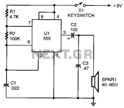
A 555 timer configured as an astable multivibrator is used in this circuit to generate an audio note. The capacitance value can be changed to vary the audio note as desired. The circuit utilizes a 555 timer IC, which...